Bolted Joint Design — Stress & Preload
Tensile & Shear Stress • Preload • Factor of Safety — Simulate • Explore • Practice • Quiz
Σ Live equations — values substituted from current state
💡 What-if coach — insights from current values
1 Overview
The Bolted Joint Design Calculator analyses the stress state and factor of safety for metric bolted connections. It covers bolt preload (clamping force), tensile stress along the bolt axis, shear stress for transverse loading, and bearing stress at the bolt-hole interface. You can select bolt sizes from M6 to M24 and property classes from 4.6 to 12.9, matching real-world ISO metric fastener specifications.
Proper bolt preload is critical for joint integrity: it keeps the clamped members in compression, prevents joint separation under external loads, and improves fatigue life. The recommended preload is typically 75–90% of the bolt’s proof load, calculated as Fi = 0.9 × At × Sp, where At is the tensile stress area and Sp is the proof strength.
2 Setting Up the Job

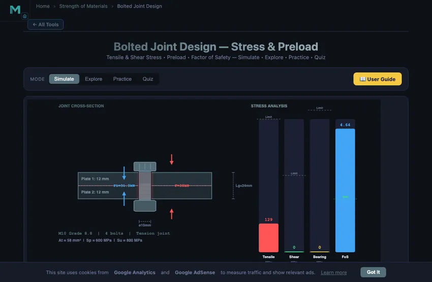
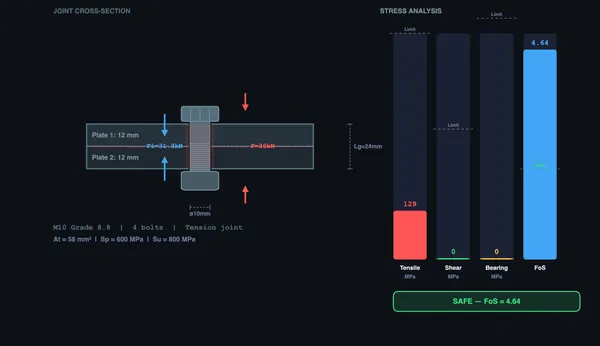
The simulator opens in Simulate mode with an M10 Grade 8.8 bolt, 4-bolt tension joint, 30 kN external load, and 12 mm plate thicknesses. The canvas shows a cross-section of the bolted joint with force arrows and stress zones. Below are controls for bolt size, grade, load, number of bolts, plate thicknesses, and joint type.
Use the Presets (Flange Joint, Bracket Mount, Pressure Vessel, Structural Joint) to load common configurations instantly. The readout cards display bolt stress, preload, factor of safety, proof load, stress area, shear stress, bearing stress, and grip length.
3 Running the Operation
Select a Bolt Size (M6–M24) from the dropdown — each size has a specific tensile stress area At that accounts for the reduced cross-section at the thread root. Choose a Bolt Grade (4.6, 5.8, 8.8, 10.9, or 12.9) — the first number × 100 gives the ultimate tensile strength in MPa, and the second number is the yield-to-ultimate ratio.
Adjust External Load (1–200 kN), Number of Bolts (1–12), and Plate Thicknesses (3–50 mm each). Select the Joint Type: Tension (axial loading along bolt), Shear (transverse loading), or Combined (both simultaneously). For combined loading, the Von Mises equivalent stress is checked: σeq = √(σ² + 3τ²).
The factor of safety = proof strength / actual stress. A value above 1.0 indicates the bolt is within safe limits. The torque specification for tightening can be estimated as T = K × Fi × d, where K is the nut factor (typically 0.2 for dry bolts).
Preload-aware bolt force. Unlike a naive “load ÷ bolts” estimate, the simulator models the joint as two springs: the bolt force is Fb = Fi + C·P, where C = kb/(kb+km) is the load ratio and P is the external load per bolt. Because C is usually only 0.15–0.35, a preloaded bolt absorbs just a small fraction of each external-load increment — the readout cards show C, the resulting bolt force Fb, and the separation load at which the joint opens. The bolt stress and factor of safety are computed from this total bolt force.
4 Speeds, Feeds & Theory
Explore mode offers 10 concepts across three categories: Bolt Basics (bolt anatomy, thread geometry, grade markings, tensile stress area), Stresses (tensile, shear, bearing, combined loading), and Design (preload calculation, torque specifications, joint stiffness, fatigue considerations).
Each concept includes a detailed explanation with diagrams. Understanding the tensile stress area calculation At = (π/4)(d − 0.9382p)² is essential — it is not simply the shank cross-sectional area but accounts for the thread root diameter.
5 Try a Problem
Practice mode generates random bolt design problems — for example, “Calculate the tensile stress in an M12 Grade 10.9 bolt under 45 kN load.” Enter your answer, click Check, and review the step-by-step solution if needed. Your running score is tracked.
Quiz mode presents 5 randomised questions covering preload calculation, stress area, shear and bearing stress, factor of safety, and bolt grade interpretation. Your score and detailed review are shown at the end.
6 Shop Tips
- Always use the tensile stress area At, not the nominal bolt area, for stress calculations involving threaded sections.
- Bolt grade 8.8 means: UTS = 800 MPa, yield = 80% × 800 = 640 MPa. Grade 10.9 means: UTS = 1000 MPa, yield = 900 MPa.
- Recommended preload is 75–90% of proof load. Under-tightening leads to joint separation; over-tightening risks bolt yield.
- For shear joints, friction-grip connections (where the bolt preload creates friction between plates) are preferred over bearing-type connections for fatigue resistance.
- Increasing the number of bolts reduces the load per bolt but requires careful spacing to avoid weakening the plate between holes.
- In combined loading, always check the Von Mises equivalent stress rather than tensile and shear independently.
- Compare the Flange Joint and Bracket Mount presets to see how joint type (tension vs. shear) changes the dominant stress mode.
7 Interface, Units & Export
- Steppers & sliders. Every numeric input (load, number of bolts, plate thicknesses) has a slider plus a [−] [value] [+] stepper — drag for speed or type/step for an exact value. The external-load range now reaches 500 kN.
- SI / Imperial units. Use the Units toggle (SI ↔ Imperial) to switch every result between kN/MPa/mm and kip/ksi/in. Inputs stay in SI (metric bolts are specified in mm); all computed outputs, canvas labels, equations and the calculation steps convert.
- Show Calculations. The calculator button on the diagram opens a step-by-step derivation (stress area → preload → stiffness/load-ratio → bolt force → factor of safety) typeset in classical notation, rebuilt from the current state every time.
- Live equations & What-if coach. The collapsible learning panels below the controls show the governing equations with your numbers substituted, plus plain-language coaching on the factor of safety, joint separation and fatigue behaviour.
- Canvas toggles. Show/hide the stress zones, dimension lines and the on-canvas equation overlay to focus on one concept at a time.
- Export & Reset. Export the full results table as CSV or the diagram as a watermarked PNG. Undo/Redo (also Keyboard: Ctrl+Z / Ctrl+Shift+Z) step through every change. Right-click the diagram for a quick Copy / Export / Reset menu.
Bolted Joint Design — Stress and Preload Analysis
Bolted joint design is a fundamental topic in mechanical engineering and machine design. Engineers use bolted connections to join structural members, flanges, brackets, and pressure vessels. Proper bolt design ensures that joints can safely carry applied loads without failure due to excessive tensile stress, shear, or fatigue. Understanding preload, stress distribution, and factor of safety is essential for reliable mechanical assemblies.
A bolted joint consists of a bolt (head, shank, and threads), nut, and the clamped parts (plates, flanges, or members). Metric bolts are classified by their nominal diameter (M6 through M24 and larger) and their property class (grade), such as 4.6, 5.8, 8.8, 10.9, and 12.9. Each grade specifies proof strength, yield strength, and ultimate tensile strength, which directly determine the bolt's load-carrying capacity.
Bolt Preload and Tensile Stress
When a bolt is tightened, it develops a preload (Fi) — a clamping force that holds the joint together even before external loads are applied. The recommended preload for reusable connections is Fi = 0.9 × At × Sp, where At is the tensile stress area and Sp is the proof strength. The tensile stress area accounts for the reduced cross-section at the thread root and is calculated as At = (π/4)(d − 0.9382p)², where d is the nominal diameter and p is the thread pitch. The tensile stress in the bolt is σ = F / At, which must remain below the proof strength with an adequate factor of safety.
Shear and Bearing Stress
In joints loaded in shear (transverse to the bolt axis), the bolt resists sliding between the plates. The shear stress is τ = F / (n × A), where n is the number of bolts and A is the bolt cross-sectional area. Bearing stress occurs where the bolt contacts the plate and is calculated as σb = F / (n × d × t), where d is the bolt diameter and t is the thinner plate thickness. For combined loading (tension plus shear), the von Mises equivalent stress must be checked against the allowable stress.
How to Use This Simulator
In Simulate mode, select a bolt size (M6 to M24), grade (4.6 to 12.9), number of bolts, external load (up to 500 kN), plate thicknesses, and joint type (Tension, Shear, or Combined). The canvas displays a cross-section of the bolted joint with force arrows, stress zones, and a stress distribution diagram — all updating in real time. Crucially, the bolt stress is computed from the preload-aware bolt force Fb = Fi + C·P (not a naive load ÷ bolts), and the tool reports the load ratio C and the joint separation load. Toggle SI / Imperial units, open Show Calculations for a step-by-step KaTeX derivation, read the live-equation and what-if-coach panels, and export results as CSV or the diagram as PNG. Switch to Explore mode to study 10 concepts across Bolt Basics, Stresses, and Design with worked examples. Practice mode generates random bolt design problems, and Quiz tests your knowledge with 5 randomised questions.
An M16 Grade 8.8 Joint — The Calculation That Lives on Every Mechanical Drawing
Take the canonical machine-design problem: design an M16 grade 8.8 bolted joint to carry a 40 kN tensile load with a safety factor of 2 against bolt yielding. Set the simulator’s preset to match. The textbook walks through it in four lines:
| Step | What it gives | Result |
|---|---|---|
| Tensile stress area (ISO 898-1 Table 4) | At for M16 × 2.0 pitch | 157 mm² |
| Proof strength of grade 8.8 | Sp = 580 MPa | — |
| Yield strength of grade 8.8 | Sy = 640 MPa | — |
| Maximum yield-limited bolt force | Fyield = Sy × At = 640 × 157 | 100.5 kN |
| Safety factor at 40 kN external load | FOS = Fyield / Fapplied = 100.5/40 | 2.51 ✓ |
| Tightening torque (Shigley Table 8-15) | T = K·Fi·d for K=0.2 and Fi = 0.9·At·Sp | ~262 N·m |
That last row is the practically useful number. To get 0.9 of proof-strength preload in an M16 grade 8.8, a normally-lubricated bolt requires about 260 N·m of torque. The simulator’s torque-input preset confirms this. With a 300 mm wrench, that is roughly 90 kgf of pull at the end of the wrench — firm two-handed effort.
Why Preload Matters More Than Bolt Strength
The most counter-intuitive fact in bolted-joint design: under cyclic loading, a properly preloaded bolt sees very little of the external load. The clamped plates and the bolt act like two springs in parallel. When you apply an external pull, both stretch slightly. Most of the load increment is absorbed by the (relatively soft) plates relaxing their compression. The bolt sees only a small fraction of the external load on top of its preload.
Numerically: for a typical steel-plate flange and a steel bolt, the bolt “stiffness fraction” (the share of external load that reaches the bolt) is about 0.20 to 0.35. So a 40 kN external load increases bolt tension by only about 10 kN. That is why pretensioned bolts are dramatically more fatigue-resistant than non-preloaded ones.
Joint Failures You Should Recognise
- Bolt thread strip. The bolt’s threads shear before the bolt body breaks. Usually means the bolt grade was too high for the nut grade, or the engagement length was too short.
- Plate hole bearing crush. The plate yields at the bolt hole rim. Common when the plate is too thin or the bolt is too small for the load. Calculate bearing stress σb = F/(n·d·t) and check.
- Joint separation under load. The external load exceeds the preload — the plates lift apart and the bolt sees the full force. Catastrophic for sealed flanges. Solution: more preload, more bolts, or stiffer plates.
- Fatigue at the first engaged thread. The thread root next to the nut face is the stress riser. Under cyclic loading, cracks initiate here. Rolled threads and proper preload are the two big defenses.
Standards and References
- ISO 898-1:2013 — Mechanical properties of fasteners made of carbon steel and alloy steel — Part 1: Bolts, screws and studs with specified property classes. The grade-table source.
- VDI 2230 — Systematic calculation of high-duty bolted joints with one cylindrical bolt. The German reference, more rigorous than Shigley for critical-application designs.
- Shigley & Mischke — Mechanical Engineering Design, 10th ed., Chapter 8. The English-language standard for the worked example above.
- BS EN ISO 6789-1:2017 — Hand torque tools. Defines the accuracy class of the wrench you need to actually achieve a target torque.
Explore Related Simulators
If you found this Bolted Joint simulator helpful, explore our Thin-Walled Pressure Vessel simulator, Riveted Joints simulator, Thread Nomenclature trainer, Power Screw Calculator, and Welding Symbols trainer for more hands-on practice.