Flywheel Energy Storage
Turning Moment Diagrams • Coefficient of Fluctuation • Energy Storage — Simulate • Explore • Practice • Quiz
1 Overview
The Flywheel Energy Storage Simulator helps you understand how flywheels store and release kinetic energy to smooth power delivery in mechanical systems. The fundamental equation is E = ½Iω², where I is the moment of inertia and ω is the angular velocity.
This tool visualises turning moment diagrams showing surplus and deficit energy regions, calculates the coefficient of fluctuation (C_s), and demonstrates flywheel sizing for engines, punch presses, wind energy systems, and braking applications. You will see how mass calculation relates to speed variation requirements.
2 Loading the Mechanism

- Select an Application (Engine, Punch Press, Wind Energy, or Braking) to load a relevant configuration.
- Adjust Mass, Radius, RPM, and Load Variation sliders.
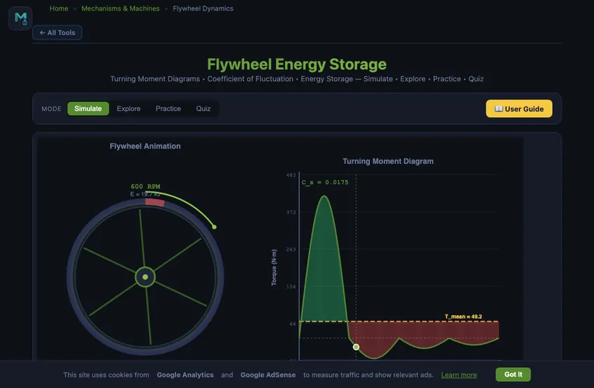
- The left canvas shows an animated spinning flywheel with energy level; the right shows the turning moment diagram.
- Readout cards display kinetic energy, moment of inertia, angular velocity, coefficient of fluctuation, mean/max torque, energy surplus, and max speed.
3 Watching the Motion
The turning moment diagram plots instantaneous torque against crank angle. Areas above the mean torque line (green) represent energy surplus — the flywheel absorbs energy and speeds up. Areas below (red) represent energy deficit — the flywheel releases stored energy. The maximum energy fluctuation determines the required flywheel size.
The coefficient of fluctuation C_s = (N_max - N_min)/N_mean determines how much speed variation is acceptable. Smaller C_s requires a larger flywheel. The required moment of inertia is I = ΔE/(ω² × C_s).
4 Geometry & Theory
Study 12 concepts across Energy Basics, Fluctuation, and Design categories. Topics include kinetic energy storage, moment of inertia for different geometries, turning moment diagrams, coefficient of fluctuation, flywheel sizing, rim stress analysis, and material selection.
5 Try a Problem
Practice generates problems on kinetic energy, moment of inertia, coefficient of fluctuation, flywheel mass, and energy surplus calculations. Quiz provides 5 randomised questions from a pool of 15.
6 Design Notes
- Energy scales with ω² — doubling the speed quadruples the stored energy, making speed the most effective design variable.
- A punch press flywheel must deliver enormous energy in a very short time — observe how the turning moment diagram changes for this application.
- For engine flywheels, C_s is typically 0.01-0.05; for crushing machines, up to 0.20 is acceptable.
- A rim-type flywheel (I = mr²) has twice the moment of inertia of a solid disc (I = ½mr²) for the same mass and radius.
- Compare all four applications to see how turning moment diagrams and required flywheel sizes differ dramatically.
Flywheel Energy Storage — Turning Moment Diagrams and Coefficient of Fluctuation
Flywheel energy storage is one of the oldest and most elegant methods of smoothing power delivery in mechanical systems. A flywheel is a heavy rotating disc mounted on a shaft that stores kinetic energy during periods of excess torque and releases it during periods of deficit. This energy buffering action is critical in internal combustion engines, punch presses, wind turbines, and braking energy recovery systems. The fundamental equation governing flywheel energy storage is E = ½Iω², where I is the moment of inertia and ω is the angular velocity in rad/s.
Understanding Turning Moment Diagrams
A turning moment diagram (also called a crank effort diagram) plots the instantaneous torque produced by an engine or machine against the crank angle over one complete cycle. For a four-stroke single-cylinder engine, the cycle spans 720° (two full revolutions). The torque varies significantly — it peaks during the power stroke and drops during compression, exhaust, and intake strokes. The mean torque is a horizontal line representing the average resisting torque. Areas above this line represent energy surplus (the flywheel absorbs energy and speeds up), while areas below represent energy deficit (the flywheel releases stored energy and slows down). The maximum energy fluctuation — the difference between maximum and minimum energy levels — determines the required flywheel size.
Coefficient of Fluctuation and Flywheel Sizing
The coefficient of fluctuation (Cs) measures the variation in flywheel speed and is defined as Cs = (Nmax − Nmin) / Nmean, or equivalently (ωmax − ωmin) / ωmean. For most industrial applications, Cs ranges from 0.002 for spinning machinery to 0.2 for crushing machines. The energy stored in a flywheel that compensates for fluctuation is given by ΔE = Iω2Cs. Rearranging this equation allows engineers to calculate the required moment of inertia: I = ΔE / (ω²Cs). For a solid disc flywheel, I = ½mr², while for a rim-type flywheel, I = mr². These equations form the basis of flywheel sizing for any mechanical application.
Applications of Flywheel Energy Storage
In reciprocating engines, the flywheel smooths out the pulsating torque from individual cylinders, ensuring steady output speed. Punch press operations require enormous torque for very brief periods — the flywheel accumulates energy over the idle stroke and delivers it instantly during the punching stroke. In wind energy systems, flywheels buffer the variable input from wind against a steady generator load. Modern regenerative braking systems use high-speed flywheels to capture kinetic energy during deceleration and return it during acceleration, improving energy efficiency by up to 30%. Advanced flywheel materials such as carbon fibre composites allow extremely high rotational speeds, enabling compact designs with energy densities exceeding 100 Wh/kg.
Sizing a Punch-Press Flywheel — A Single Worked Example
A punch press needs 30,000 J of work per punch, and punches 60 times per minute. The motor delivers steady mean power. The press has ω = 100 rad/s (about 955 rpm) and a coefficient of fluctuation Cs = 0.05 (5% speed variation allowed). Specify the flywheel.
| Step | Working | Result |
|---|---|---|
| Mean motor power (60 punches/min) | P = 30,000 J × 1 punch/s | 30 kW |
| Energy fluctuation (full punch over deficit period) | ΔE ≈ 30,000 J (worst case) | 30 kJ |
| Required moment of inertia | I = ΔE/(Cs·ω²) = 30,000/(0.05×100²) | I = 60 kg·m² |
| Solid disc: I = ½mr². Pick r = 0.4 m | m = 2I/r² = 120/0.16 | 750 kg |
| OR rim-type flywheel (I = mr²): pick r = 0.4 m | m = I/r² = 60/0.16 | 375 kg (half the mass) |
| Energy stored at operating speed | E = ½Iω² = ½×60×100² | 300 kJ |
The rim-type flywheel stores all its mass at the maximum radius, giving twice the moment of inertia per kg. This is why real punch-press flywheels look like heavy hoops, not solid discs. The 30 kJ per punch is 10% of stored energy — the press slows by ~5% during each punch and recovers between punches.
Why a Tiny Motor Can Drive a Massive Punch Press
The trick is the time scale. A punch happens in maybe 0.1 second. If the motor had to deliver 30,000 J in 0.1 s directly, it would need 300 kW — the size of a small lorry engine. With a flywheel buffering the load over a full second, the motor only needs 30 kW — one tenth the size. This is why every industrial punch press, plate shear, forging hammer, and stamping machine has a heavy flywheel between the motor and the load: it lets you use a small steady motor for a big intermittent job.
The same principle, in reverse, is why backup uninterruptible power supplies sometimes use flywheels instead of (or alongside) batteries. The flywheel can deliver megawatts for tens of seconds — enough to bridge a power interruption while a backup diesel generator starts.
Modern Flywheel Energy Storage — Beyond the Punch Press
Carbon-fibre flywheels spinning at 50,000−100,000 rpm in vacuum chambers on magnetic bearings achieve energy densities of 100−200 Wh/kg — comparable to lithium-ion batteries with two advantages: cycle life of millions of cycles (vs thousands for batteries), and instantaneous response time. Where they live today:
- Grid frequency regulation. Beacon Power and others installed 20−25 MW flywheel facilities for AC grid frequency support, responding in milliseconds.
- Formula 1 KERS (2009−2013). Williams Hybrid Power supplied a 60,000 rpm carbon-fibre flywheel storing 400 kJ — recovered braking energy and fed it back into the powertrain. Effective but heavy and complex; current F1 uses battery-electric hybrid instead.
- Subway regenerative braking. London Underground tested wayside flywheels at the trackside to absorb braking energy from incoming trains; less common than battery storage now but a viable variant.
- Data-centre uninterruptible power supplies. Active Power and others sell flywheel UPS units that bridge the 8−30 seconds between mains failure and backup generator start.
Why Flywheels Don’t Store as Much as Batteries Anymore
Energy density E/m = ½·k·σtensile/ρ where k is a shape factor. The tensile strength limits how fast you can spin before centrifugal stress tears the rotor apart. Steel: about 5 Wh/kg. Carbon fibre: about 200 Wh/kg. Both fall short of modern lithium-ion (~250 Wh/kg) and well short of fuel (~12,000 Wh/kg for petrol). Flywheels won’t replace batteries for energy storage; they win on power density, cycle life, and response time. Different niche.
References
- Khurmi, R. S. — Theory of Machines, 14th ed., Chapter 16 (Flywheel). The widely-used Indian engineering textbook treatment.
- Beacon Power Corporation — technical white papers on grid-scale flywheel storage.
- Genta, G. — Kinetic Energy Storage, Butterworth-Heinemann. The graduate reference for high-speed composite flywheels.
Explore Related Simulators
If you found this Flywheel simulator helpful, explore our Flywheel Energy Storage simulator, Slider-Crank simulator, and Governor simulator for more hands-on practice.