Moment of Inertia — Simulation Trainer
Ix, Iy, Section Modulus, Radius of Gyration • 8 Cross-Sections • Parallel Axis Theorem — Simulate • Explore • Practice • Quiz
Σ Live equations — formulas + values for the current shape
💡 What-if coach — design insights from current values
1 Overview
This free moment of inertia calculator computes the second moment of area (Ix, Iy), section modulus (Sx, Sy), radius of gyration (rx, ry), polar moment of inertia (J), and centroid for eight standard cross-sections. The interactive canvas draws each shape to scale with dimension lines, centroid markers, and neutral axes, providing an engineering-grade visualisation of cross-section geometry.
Supporting shapes include rectangle, circle, hollow circle, hollow rectangle, I-beam, T-section, channel section, and angle section. The parallel axis theorem (I = Ic + Ad²) is used automatically when computing properties of composite shapes like T, channel, and angle sections.
2 Entering the Inputs

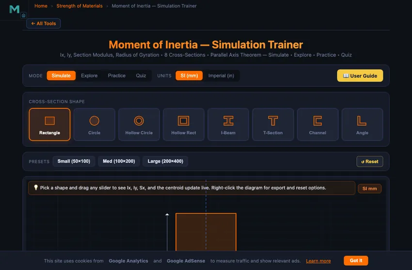
The simulator opens in Simulate mode with the Shape Selector visible above the canvas. Click any shape icon to select it; the canvas immediately draws the cross-section with dimension lines and the centroid marked. Sliders with companion stepper inputs appear below the canvas, and readout cards display all computed properties.
Use the Mode pills to switch between Simulate, Explore, Practice and Quiz. Use the Units pills to toggle between SI (mm) and Imperial (in) — all sliders, readouts, dimension labels and the calculation modal convert simultaneously.
3 Simulate Mode — Controls
Each shape dimension has both a slider and a companion stepper input [−] [text] [+] […]. Drag the slider for quick exploration, type into the text input for an exact value, click the +/− buttons to nudge by 1 mm (or 0.1 in), or click the … button to open the Custom Value modal for values beyond the slider range (real-world structural sections).
Presets for standard sections (IPE, HE, UPN, RHS, SHS, pipes, rods) appear above the canvas — one click loads textbook-grade dimensions. The Reset preset restores the default values for the current shape.
Canvas feature toggles let you show/hide the grid, axes, centroid marker, and dimension lines independently — useful for focusing on a single concept during teaching.
4 Show Calculations & Learning Panels
Click the orange Show Calculations button at the bottom-right of the canvas to open a step-by-step derivation of every property for the current shape and dimensions. The modal uses classical mathematical notation rendered with KaTeX, with each step boxed and showing the formula, the substituted values, and the result in both SI and Imperial units.
Below the canvas, two collapsible Learning panels show Live equations (the LaTeX formulas with current values substituted) and the What-if coach (design insights based on the current Ix/Iy ratio, slenderness, and shape efficiency). Use the Expand all / Collapse all buttons to control them as a group.
5 Export, Undo, and Right-click Menu
Export CSV generates a comma-separated file with every input dimension and every computed property in both SI and current display units. Export PNG snapshots the canvas with a watermark for use in lecture slides or lab reports. Both buttons live above the readout cards; both are also available from the right-click context menu on the canvas.
Keyboard shortcuts: Ctrl+Z to undo, Ctrl+Shift+Z (or Ctrl+Y) to redo. The undo stack covers shape changes, slider values, preset loads, unit toggles, and feature-toggle clicks (60-step history).
6 Explore, Practice & Quiz
Explore mode provides concept cards across four categories: Basics (definition, centroid, S, r, J), Shapes (rectangle, circle, hollow, I-beam formulas), Theorems (parallel axis, perpendicular axis), and Applications (beam design, column buckling, shaft torsion). Every formula is rendered with KaTeX in classical notation.
Practice mode generates random problems with full step-by-step solutions. Quiz mode presents 5 randomised questions per session covering shape identification, formula application, parallel axis theorem, and section modulus calculations.
7 Tips & Best Practices
- Compare shapes: Use Presets and the readout cards to compare standard sections at a glance.
- I-beam efficiency: Increase flange width while keeping web height constant to see Ix grow dramatically.
- Parallel axis theorem: Open the Show Calculations modal on a T-section, channel, or angle to see the Ic + Ad² breakdown.
- Section modulus shortcut: S = I/c — for unsymmetric sections, the modal uses c_max automatically.
- Imperial mode: All internal math stays in SI; only labels and readouts convert — rounding errors are zero.
- Custom values: Slider ranges cap at common educational sizes; use the … button for real structural sections (e.g. 600 mm depth, 12 in flanges).
Moment of Inertia — Cross-Section Properties Calculator
The moment of inertia (also called the second moment of area) is one of the most important geometric properties in structural and mechanical engineering. It quantifies how a cross-section's area is distributed relative to an axis, directly determining a beam's resistance to bending. A larger moment of inertia means greater stiffness and lower deflection under load. Engineers use moment of inertia calculations daily when designing beams, columns, shafts, and structural frames.
This free moment of inertia calculator lets you compute Ix, Iy, section modulus (Sx, Sy), radius of gyration (rx, ry), and polar moment of inertia (J) for eight standard cross-sections: rectangle, circle, hollow circle, hollow rectangle, I-beam, T-section, channel section, and angle section. The interactive canvas draws each shape to scale, and the built-in step-by-step calculation modal renders every formula in classical LaTeX notation through KaTeX. SI and Imperial units toggle instantly for international classroom use.
How to Calculate Moment of Inertia for Common Shapes
For a rectangular cross-section with width b and height h, the moment of inertia about the centroidal horizontal axis is Ix = bh³/12. For a circular cross-section with diameter d, both Ix and Iy equal πd&sup4;/64. Hollow sections are calculated by subtracting the inner shape's moment of inertia from the outer. For example, a hollow circular tube has Ix = π(D&sup4; − d&sup4;)/64. The I-beam, widely used in structural steel construction, achieves a high Ix relative to its area by concentrating material in the flanges far from the neutral axis.
The Parallel Axis Theorem and Composite Sections
The parallel axis theorem states that I = Ic + Ad², where Ic is the centroidal moment of inertia, A is the area, and d is the distance between the centroid and the new axis. This theorem is essential when computing the moment of inertia of composite sections like T-beams, channels, and angle sections, where individual component areas are offset from the overall centroid. The section modulus S = I/c connects moment of inertia to bending stress through the flexure formula σ = M/S, making it a direct measure of a beam's load-carrying capacity.
Section Modulus, Radius of Gyration, and Design Applications
The radius of gyration r = √(I/A) represents the distance from the axis at which the entire area could be concentrated to produce the same moment of inertia. It is critical in column buckling analysis using Euler's formula Pcr = π²EI/L², where a higher radius of gyration means greater resistance to buckling. In shaft design, the polar moment of inertia J determines torsional rigidity through the relationship τ = Tc/J, where T is the applied torque. Understanding these properties allows engineers to optimise cross-sections for weight, strength, and stiffness.
Why I-Beams Look the Way They Do — The Geometry Argument
An I-beam is not an aesthetic choice. It is the natural geometry that drops out of bending mechanics. Bending stress varies linearly with distance from the neutral axis: zero at the centre, maximum at the top and bottom fibres. Material near the neutral axis carries almost no stress; material at the top and bottom carries it all. So a sensible cross-section concentrates mass at the top and bottom (the flanges), with just enough web in between to keep the flanges from buckling sideways.
Compare a solid 100×100 mm square beam (mass per metre ~78 kg for steel) with a 200×100 mm I-beam of the same mass (10 mm flanges, 6 mm web). The I-beam’s second moment of area is roughly five times higher. Same material, same cost — five times the stiffness. This is why every steel-framed building in the world uses I-beams instead of square stock for the load-bearing members.
The Parallel-Axis Theorem in Action — T-Beam Calculation
Take a T-section: 100 mm wide flange, 20 mm thick, sitting on top of a 100 mm tall, 20 mm wide web. Find Ix about the centroidal axis of the whole T.
| Step | Working | Result |
|---|---|---|
| Area of flange | Af = 100×20 | 2000 mm² |
| Area of web | Aw = 100×20 | 2000 mm² |
| Total area | A = 4000 mm² | — |
| Centroid (from bottom) | &ybar; = (2000×50 + 2000×110)/4000 | 80 mm |
| Iflange about its own centroid + Ad² | 100×20³/12 + 2000×(110−80)² | 1,866,667 mm&sup4; |
| Iweb about its own centroid + Ad² | 20×100³/12 + 2000×(80−50)² | 3,466,667 mm&sup4; |
| Total Ix about whole-T centroid | sum | 5.33×106 mm&sup4; |
The parallel-axis theorem trick: calculate each part’s I about its own centroid, then add A×(distance to the new axis)². The “Ad²” term is usually larger than the “Ic” term — geometry matters more than the shape of each part.
Why Figure Skaters Spin Faster When They Pull Their Arms In
Same theorem, dynamic form. The polar moment of inertia of a skater with arms outstretched might be 4 kg·m²; arms tucked in, 1 kg·m². Angular momentum L = Iω is conserved during the spin (no external torque). So if I drops by 4×, ω rises by 4×. A skater spinning at 1 rev/s with arms out spins at 4 rev/s with arms in — visually astonishing, mathematically obligatory.
References for Cross-Section Properties
- Hibbeler — Mechanics of Materials, 10th ed., Appendix A (Geometric Properties).
- AISC Steel Construction Manual — tabulated properties for every standard W-section, S-section, HSS and angle.
- BS 4-1:2005 / EN 10025 — the European steel I-beam standard.
- Roark's Formulas for Stress and Strain — the engineer's quick reference for non-standard cross-section properties.
Explore Related Simulators
If you found this Moment of Inertia simulator helpful, explore our Beam Bending Calculator, Shaft Torsion Simulator, Truss Analysis Simulator, and Pressure Vessel Calculator for more hands-on practice.