
Ray Optics Simulator & Trainer
Mirrors & Lenses — Simulate · Explore · Practice · Quiz
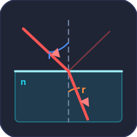
Adjust the sliders and press Trace Rays to see how the image forms.
User Guide
1 Overview
The Ray Optics Simulator & Trainer lets you explore how light interacts with mirrors and lenses. Choose between concave and convex optics, set object position and focal length, then trace rays to see where the image forms — its position, size, and orientation.
Four modes: Simulate (interactive ray tracing), Explore (educational cards), Practice (unlimited problems), and Quiz (5-question assessment).
2 Setting Up the Rig

Select an optic type (Mirror or Lens) and a sub-type (Concave or Convex). Adjust the sliders for object distance, height, and focal length. Press Trace Rays to see the animated ray diagram. You can also drag the object arrow directly on the canvas.
3 Running the Test
Three principal rays animate from the object through the optic, forming the image. The formula panel shows the live calculation. Readout badges display u, v, f, magnification, and image nature. Drag the object arrow to explore different positions in real time.
Right-click the canvas to save as image, copy the current reading, or reset.
4 Background Theory
Five educational categories: Basics (light and reflection), Mirrors (concave/convex behaviour), Lenses (convex/concave behaviour), Formulas (mirror/lens equations with worked examples), and Applications (telescopes, cameras, corrective lenses).
5 Practice Problems
Practice: Solve unlimited ray optics problems — predict image distance, nature, magnification, or identify the optic type from given properties. Instant feedback with explanations.
Quiz: 5 randomly selected questions. Scored with a star rating (3 stars = perfect). Review each answer after completion.
6 Key Concepts
Mirror equation: 1/f = 1/v + 1/u (Cartesian sign convention)
Lens equation: 1/f = 1/v − 1/u
Magnification: mirror m = −v/u, lens m = v/u — both equal image height / object height
Sign convention: Distances towards incident light are negative, away are positive. Object distance u is always negative.
7 Tips & Best Practices
- Try placing the object at F, at 2F, and beyond 2F to see how the image changes.
- Switch between concave and convex to compare real vs virtual images.
- Use Explore mode to understand the sign convention before attempting Practice.
- Audio click plays on drag start; success/error tones play in Practice and Quiz.
Understanding Ray Optics: Mirrors and Lenses


What Is Ray Optics?
Ray optics (geometric optics) is the branch of physics that describes light propagation in terms of rays. When light strikes a mirror it reflects; when it passes through a lens it refracts. By tracing just three principal rays from any point on an object, we can predict exactly where the image will form, how large it will be, and whether it is real or virtual.
Concave vs Convex: Mirrors and Lenses
A concave mirror converges parallel light to a real focal point, producing real inverted images when the object is beyond the focal length. A convex mirror always diverges light, producing virtual, erect, diminished images — which is why convex mirrors are used as rear-view mirrors. Similarly, a convex lens converges light and can form both real and virtual images, while a concave lens always diverges light, forming virtual images used to correct myopia.
The Mirror and Lens Equations
Using the Cartesian sign convention, the mirror equation is 1/f = 1/v + 1/u, and the thin lens equation is 1/f = 1/v − 1/u. Here u is the object distance (always negative), v is the image distance, and f is the focal length. Magnification tells us the size ratio and orientation, and it too differs by a sign between the two optics: m = −v/u for a mirror, m = v/u for a lens. Dropping that minus sign on a mirror problem reports an inverted image as erect — it is the most common slip in the topic. Note also that a concave mirror’s real image forms in front of the mirror, on the same side as the object, whereas a convex lens’s real image forms on the far side.
A Worked Lens Equation Example — Camera Focus
A camera lens with focal length 50 mm photographs an object 2 m away. Where does the image form, and what is the magnification?
| Step | Working | Result |
|---|---|---|
| Convert to consistent units | f = 50 mm = 0.050 m, u = −2 m | — |
| Apply thin lens equation | 1/v = 1/f + 1/u = 1/0.050 + 1/(−2) | 1/v = 20 − 0.5 = 19.5 |
| Image distance | v = 1/19.5 | v = 51.3 mm |
| Magnification | m = v/u = 51.3/(−2000) | m = −0.0256 |
| Image size of a 0.5 m object | 0.0256 × 500 | 12.8 mm (inverted) |
Note that v (51.3 mm) is only slightly larger than f (50 mm). For distant objects (u much larger than f), the image always forms close to the focal plane — which is why every camera sensor is positioned approximately at the focal length behind the lens. Refocusing for closer objects simply means moving the sensor a fraction of a millimetre further from the lens. Modern autofocus systems do this in milliseconds.
The Sign Convention — Where Most Students Get Lost
Sign conventions in optics are notoriously confusing because different textbooks use different ones. The simulator uses the most common Cartesian convention: distances measured from the lens centre; rightward positive; upward positive; converging lens has positive f; diverging lens has negative f. Real images have positive v (formed on the side opposite the object); virtual images have negative v (formed on the same side as the object).
With this convention: convex lens with object beyond f gives a positive v (real image, inverted, opposite side). Concave lens always gives negative v (virtual image, upright, same side). Object inside f of a convex lens (used as a magnifying glass) gives negative v (virtual image, upright, magnified, same side). The simulator marks these with colour and explicit labels so the geometry stays clear.
Real Engineering Optics — Where Ray Tracing Lives
- Camera and phone lenses. Modern lenses use 8−15 elements to correct for aberrations that single lenses can’t fix — chromatic aberration, spherical aberration, coma, distortion. Each surface is a refracting interface to be ray-traced.
- Microscopes and telescopes. The same equations describe both, with magnification scaling per stage. A research microscope chains 4−6 optical assemblies; final magnification is the product.
- Eyeglass prescriptions. A −3.00 D prescription for myopia means a concave lens with focal length −33 cm, designed to push the eye’s effective image plane onto the retina rather than in front of it.
- Laser focusing. Used in laser cutting, semiconductor lithography, optical communication. Same equations, but with attention to Gaussian beam diffraction limits that geometric optics misses.
References
- Hecht, E. — Optics, 5th ed., Pearson. The undergraduate standard.
- Born & Wolf — Principles of Optics, 7th ed., Cambridge. The graduate reference.
- Sidney F. Ray — Applied Photographic Optics, 3rd ed. Practical lens design for photographers and engineers.
Explore Related Simulators
Continue your physics exploration with the Refraction of Light Simulator for Snell’s law, the critical angle and total internal reflection, Beam Bending Simulator for structural mechanics, Litmus Test Virtual Lab for chemistry fundamentals, Spring Design Calculator for elastic mechanical systems, or the Stress-Strain Curve Simulator for material behaviour.
Updated