Screw Gauge Simulator
Interactive precision measurement trainer — LC = 0.01 mm
1 Overview
This micrometer screw gauge simulator is a free online tool for practising how to read a micrometer. It supports both SI (metric) and Imperial (inch) micrometers as fully independent instruments. In SI mode, the micrometer has a 0.01 mm least count with 50 thimble divisions. In Imperial mode, a standard 0.001″ least count micrometer with 25 thimble divisions is used. Four modes — Simulate, Explore, Practice, and Quiz — guide you from learning theory to hands-on measurement mastery.
2 Setting the Zero


The simulator opens in Simulate mode with SI units and the micrometer set to a default reading. To begin:
- Drag the thimble left or right to change the measurement. Use arrow keys for fine step adjustments, or Shift+arrow for full-revolution steps (0.5 mm / 0.025″).
- Watch the info row update in real time — it shows the reading, MSR, CSR, LC, and the full TR formula.
- Toggle SI / Imperial to switch between a metric micrometer (0–15 mm) and an inch micrometer (0–1″). The entire scale redraws with correct divisions.
- Use the Zoom button (or press Z) to magnify the reading area where the thimble meets the barrel.
3 Taking a Reading

In Simulate mode the micrometer responds freely to dragging. As you rotate the thimble, observe how the barrel exposes or covers the scale marks, and how the thimble division aligns with the datum line. Audio feedback provides subtle click and tick sounds as you drag. The formula panel shows the step-by-step calculation live. Use this mode to build confidence before moving to Practice.
3b Measuring a Real Object
In Simulate mode, the Measure an object button at the bottom-right of the canvas puts a real workpiece between the anvil and the spindle. Pick from eight parts — steel wire, sheet strip, 1/4″ ball bearing, dowel pin, drill shank, M5 hex nut, shim blade and brass rod.
- Choose a part. It rests against the anvil and the spindle backs fully off, exactly as you would start a real measurement.
- Drag the thimble left (or press ←, or use Close onto part). The spindle stops dead on the part — it cannot be driven through it, whatever you do.
- At contact the part shows green contact marks, a click sounds, and the dimension line beneath it reveals the true size.
- Now read the scales as usual: MSR + (CSR × LC).
Try the 1/4″ ball both ways. It is 6.35 mm exactly, so the metric micrometer reads 6.35 mm and the imperial one reads a clean 0.250″ — same part, same gap, two instruments. Most other parts don't convert so neatly: a 1.62 mm wire is 0.0638″, which a 0.001″ micrometer can only resolve to 0.064″. That gap is the resolution limit, and the object bar spells it out.
Turn Zero Error on while a part is loaded: the spindle still stops at the true size, but the scales read high or low until you apply the correction — the exact trap that spoils real measurements.
3c “Show me How?” — Guided Reading
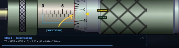
The round play button at the bottom-right of the instrument, beside Measure an object, starts a guided reading of whatever is currently on the micrometer. Every arrow, highlight and count is drawn on the scales themselves, and every number comes from the same calculation the readout tiles use.
- Step 1 — Main Scale Reading. A measuring line grows along the sleeve to the thimble's leading edge and an arrow marks the last graduation it uncovered. The caption names the trap for the screw you have fitted — the half-millimetre marks on the 0.5 mm screw, their absence on the 1 mm × 100 one, the 0.025″ divisions in Imperial.
- Step 2 — Find the division on the datum. The datum line is extended across the thimble and the neighbours either side are rejected in turn, so you can see the reading is the only one level with it.
- Step 3 — Read the thimble. The count starts at the nearest numbered graduation and steps the last few divisions to the datum — how the instrument is actually read, rather than counting from zero.
- Step 4 — Total Reading, revealed row by row, with the rod or jaw term included on the depth and inside instruments.
- Step 5 — Zero error, shown only when there is one.
On a depth or inside micrometer the walkthrough follows the reversed sleeve: the value is the last number the thimble has covered, and the arrow points at that graduation under the thimble lip.
Controls: Space play/pause, →/← next and previous step, Esc to close, or the four buttons on the canvas. Turning the thimble, changing screw, unit or instrument, or loading a part ends the walkthrough — the steps were built for the reading that was on the instrument when you started it.
It is hidden in Quiz mode, and in Practice until your answer has been marked.
4 How the Scale Works

Explore mode is a reference library of micrometer concepts, organised into five categories:
- Parts & Components: An interactive, labelled diagram of the instrument. Hover (or tap) any of the ten numbered callouts — U-frame, anvil, spindle, lock nut, sleeve, main scale, datum line, thimble, circular scale and ratchet stop — and the part lights up on the drawing while its description, specifications and workshop tips appear alongside.
- Micrometer Types: Outside, Inside, Depth, and Digital micrometers — learn the differences, ranges, and applications.
- Least Count: Worked examples for metric (0.01 mm) and imperial (0.001″) with the LC formula.
- Zero Error: No error, positive error, and negative error with correction formulas and procedures.
- Reading Method: Step-by-step guide — read MSR, find CSR alignment, calculate TR, avoid common errors.
Click any card in the grid to view its detailed information panel below.
5 Practice Readings
Practice mode offers two drills side by side, and starting one ends the other so there is only ever a single target:
- Play / Pause — click Play to animate the micrometer, then Pause to freeze it at a random reading. Read the scales and type the total reading.
- Measure an object — loads a random workpiece against the anvil. Close the spindle onto it (drag, ←, or Close onto part), then read the scales. Check stays greyed out until the faces are genuinely in contact, so the measuring step cannot be skipped.
Instant feedback with sound follows Check, and only then is the part's true size revealed. New starts the next challenge and hands the bar back to the Play drill. Your running score is displayed.
Quiz mode: a sequence of 5 questions, of which at least two are always object-measuring tasks — the rest preset the spindle for you to read. For an object question the part arrives with the spindle backed off and Submit stays locked until you have closed onto it. After all 5, a results panel shows your score with star ratings and a row-by-row breakdown. Quizzes work in both SI and Imperial, with or without zero error.
Different parts, different sizes. Practice and Quiz draw from a separate set of workpieces to the ones in Simulate, so a size you have already met cannot simply be recalled — it still has to be measured.
6 Understanding the Reading
The micrometer reading has two components:
- MSR (Main Scale Reading): In SI, count the whole and half-mm marks on the barrel. In Imperial, count the 0.025″ marks.
- CSR (Circular Scale Reading): The thimble division aligning with the datum line. Multiply by the LC.
SI example: Barrel shows 5.5 mm, thimble reads 23 → TR = 5.5 + (23 × 0.01) = 5.73 mm.
Imperial example: Barrel shows 0.275″, thimble reads 14 → TR = 0.275 + (14 × 0.001) = 0.289″.
7 SI vs Imperial Micrometer
This simulator includes three fully independent outside micrometers — plus a depth micrometer on the Instrument pills (see 7b):
- SI (Metric), 0.5 mm × 50: Pitch = 0.5 mm, 50 thimble divisions, LC = 0.01 mm, range 0–15 mm. Whole millimetres above the datum line, half millimetres below.
- SI (Metric), 1 mm × 100: Pitch = 1 mm, 100 thimble divisions, LC = 0.01 mm. The same least count — but the sleeve carries only whole-millimetre marks.
- Imperial (Inch): Pitch = 0.025″, 25 thimble divisions, LC = 0.001″, range 0–1″. Barrel divided into 40ths of an inch.
Toggle units with the SI / Imperial pills and the metric screw with the Screw pills. The entire scale, tick marks, labels, readouts, formula, and practice/quiz answers update automatically. The Screw pills are hidden in Imperial: there is no 100-division inch thimble, because 0.025″ ÷ 100 = 0.00025″ is not a graduation anyone makes.
Why a second metric screw? Not for precision — both read 0.01 mm. It is there to make the half-millimetre mark visible as a choice rather than a trap. Set a part to 5.73 mm and switch screws: the barrel jumps from 5.50 to 5.00 and the thimble from 23 to 73, while the total never moves. Missing the half-millimetre mark — and reading 5.23 instead of 5.73 — is the commonest metric micrometer error there is, and on the 1 mm screw it cannot happen. It is also the instrument in the standard exam question, “pitch is 1 mm and there are 100 divisions — find the least count”.
7b Depth Micrometer Mode
Set the Instrument pills to Depth and the simulator fits a depth micrometer — a flat base bridging a bored block, with an extension rod the screw drives into it. It uses the same screw as the outside micrometer, so the least count is still 0.01 mm (0.001″ in Imperial) and the formula is still MSR + (CSR × LC). Two things change:
- The sleeve counts backwards. The rod goes into the hole, so the thimble travels towards the base and covers the sleeve instead of uncovering it. The main scale reading is the first number hidden by the thimble. Read it like an outside micrometer and you get range − actual: a true 6.00 mm reads as 19.00 mm.
- The rod adds to the reading. Pick a rod with the Rod pills (0–25, 25–50, 50–75, 75–100 mm). The formula card grows a Rod term and the readout shows the total depth.
Measure a feature (the button on the canvas) loads one of six real machined features — keyway, counterbore, blind hole, slot, bearing housing bore, die pocket — drawn in section so the rod is visible going into the cavity and bottoming on its floor. The right rod is fitted for you in Simulate; change it by hand and the instrument tells you if it cannot reach. Drag the thimble and it follows your pointer: drag left to sink the rod, right to withdraw it.
The Screw pills disappear in Depth mode — a depth micrometer is built on the 0.5 mm screw and there is no 1 mm version to fit. Practice and Quiz fit a random rod each round, so checking which rod is in the instrument before you write the number down becomes a habit. Answer with the screw reading alone and it is marked wrong — by exactly one rod.
Explore → Parts & Components switches to the depth micrometer's own labelled diagram: base, reference plane, extension rod, lock ring, sleeve, the reversed sleeve scale, thimble, circumferential scale and ratchet stop.
7c Inside Micrometer Mode
Set the Instrument pills to Inside for a caliper-type inside micrometer — two carbide jaws that press outwards against a bore. Same screw, same 0.01 mm least count, and it shares both of the depth micrometer’s quirks:
- The sleeve counts backwards, for the same reason, so the main scale reading is the first number hidden by the thimble.
- The jaws are the base. They are 5 mm wide, so a closed instrument reads 5.00 mm, not zero — it is a 5–30 mm tool (0.2–1.2″ in Imperial). The Jaws chip states the range; unlike a depth micrometer’s rods it is not a choice, because the jaws do not come off.
Measure a bore loads one of six real features drawn in section — valve guide, slot, bearing seat, tube bore, setting ring and cylinder — and you can watch the jaws open until they touch both walls. The setting ring is there for a reason: an inside micrometer cannot be zeroed by closing it, so it is set against a certified ring.
8 Zero Error Simulation

The Zero Error control in the toolbar is off by default. Switch it On to simulate a miscalibrated micrometer, then use the − / + stepper to set an error of up to ±5 least-count divisions (i.e. ±0.05 mm in SI or ±0.005″ in Imperial).
- The simulator treats the canvas reading as the observed value. The yellow Zero Error card shows the calibration offset; the green Corrected card shows the true measurement: Corrected = Observed − Zero Error.
- In Practice and Quiz modes, each question is generated with a random zero error so you must subtract it from the observed reading before entering your answer.
- Turn the toggle Off at any time to return to a perfectly calibrated instrument.
9 Tips & Best Practices
- Always check for zero error before measuring — close the spindle onto the anvil and verify the reading is exactly 0.00 mm (or 0.000″).
- Use the ratchet stop (on a real micrometer) to apply consistent measuring force.
- Pay careful attention to the half-millimetre mark (SI) or the 0.025″ mark (Imperial) — missing it causes a 0.5 mm or 0.025″ error.
- Practice with both unit systems to prepare for different micrometers in exams and industry.
- Use Explore mode to review theory and formulas before attempting Practice or Quiz.
- Load a real workpiece (the Measure-an-object button) and close onto it — feeling the spindle stop on the part is the habit that transfers to the real instrument.
How to Use a Micrometer Screw Gauge — Online Reading Practice

A micrometer screw gauge is a precision measuring instrument that measures small lengths and diameters with a least count of 0.01 mm. It is widely used in machining, quality control, and metrology. This free online simulator lets you practise reading the barrel (sleeve) and thimble scales without needing a physical instrument.
Screw Gauge 3D Simulation — Turn the Micrometer in 3D
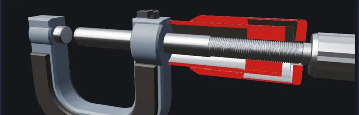
Press 3D in the top-left corner of the instrument, or open the screw gauge in 3D directly, and the same micrometer appears as a solid model you can turn and look around. It is not a video or a picture: drag the thimble or the ratchet to turn the spindle, drag the background to look at it from another side, and pinch or use the mouse wheel to zoom. The sleeve and thimble carry the real engraving, so the 3D model gives the same reading as the 2D scales beside it, to the same 0.01 mm.
There are four camera views:
- Reading — close in on the sleeve and thimble, square to the scales, the way you would read a real one.
- Whole — the complete instrument: U-frame, anvil, spindle, lock, sleeve, thimble and ratchet.
- Cutaway — the sleeve and thimble cut open to show the screw thread inside, which is the whole idea behind the least count: pitch ÷ thimble divisions.
- Parallax — move your eye off square with the slider and see how far the reading appears to shift, counted in thimble divisions. This is why a micrometer is read with the datum line straight in front of you.
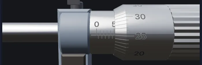
The 3D view works with all three instruments (outside, depth and inside micrometers), in SI and Imperial, with both metric screws and every depth rod. Practice, Quiz and Show me How? all run in 3D: in Practice and Quiz the model hides the reading until your answer is marked, and Show me How? moves the camera to each graduation as it explains the reading. It runs in any modern browser on a phone, tablet or computer, with nothing to install. If a device cannot show 3D, the simulator stays in the 2D view.
Step-by-Step: How to Read a Micrometer
Step 1 — Main Scale Reading (MSR): Read the last visible millimetre and half-millimetre mark on the barrel that is exposed by the thimble edge. Step 2 — Circular Scale Reading (CSR): Read which thimble division aligns with the datum line on the barrel. Step 3 — Total Reading: Apply TR = MSR + (CSR × 0.01) mm.
Micrometer Screw Gauge Principle
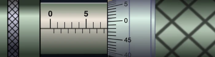
The micrometer uses the screw principle: one full rotation of the thimble advances the spindle by 0.5 mm (the pitch). With 50 divisions on the thimble scale, each division = 0.5 ÷ 50 = 0.01 mm — the instrument's least count.
What Is the Least Count of a Micrometer with 1 mm Pitch and 100 Divisions?
0.01 mm. Least count is pitch divided by the number of circular scale divisions, so 1 mm ÷ 100 = 0.01 mm — exactly the same least count as the usual metric micrometer, which gets there with a 0.5 mm pitch and 50 divisions. A finer thimble does not automatically mean a finer instrument; what matters is the ratio.
What does change is how the reading is split between the two scales. The same 5.73 mm part reads:
| Screw | Barrel (MSR) | Thimble (CSR) | Total |
|---|---|---|---|
| 0.5 mm pitch, 50 divisions | 5.50 mm | 23 | 5.73 mm |
| 1 mm pitch, 100 divisions | 5.00 mm | 73 | 5.73 mm |
The 1 mm screw has one real advantage for a learner. Because the spindle advances a whole millimetre per turn, its sleeve carries only whole-millimetre graduations — there is no half-millimetre mark below the datum line at all. Overlooking that mark, and reporting 5.23 mm for a part that measures 5.73 mm, is the single commonest metric micrometer error, and this instrument cannot make it. Switch between the two with the Screw pills and watch the barrel reading move while the total stays where it is.
Note that 0.5 mm remains the manufacturing standard: a finer pitch gives a trained hand more control per degree of thimble rotation, which is why almost every micrometer you will pick up in a workshop is a 0.5 mm × 50.
“Show me How?” — Watch the Reading Being Taken, Step by Step
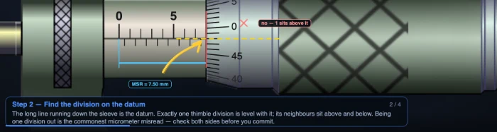
Press Show me How? — the round play button at the bottom-right of the instrument — and the simulator takes the reading currently on the micrometer and works through it on the metal itself, one step at a time. Nothing is read off a side panel; the arrows, the extended datum line and the running count are drawn on the scales you are being taught to read, and every number comes from the same calculation the readout tiles use.
- Main scale reading. A measuring line grows along the sleeve to the thimble's leading edge, a red index line marks that edge, and an arrow lands on the last graduation it uncovered. The caption names the trap for the instrument you are holding: on the 0.5 mm screw it reminds you that the marks below the datum are the half-millimetres; on the 1 mm × 100 screw it points out there are no half-millimetre marks to miss at all.
- Find the division on the datum. The datum line is extended across the thimble face and the divisions either side are probed in turn — above the line, above, level, below. Landing one division out is the commonest micrometer error, and the only cure is seeing the neighbours rejected.
- Read the thimble. You do not count to 48 on a micrometer, so neither does the walkthrough: it takes the nearest numbered graduation and steps the last few divisions from it to the datum, showing the running value one least count at a time.
- Total reading. The TR card's own rows are revealed one at a time, in the order you would write them — including the rod or jaw term on the depth and inside instruments.
- Zero error — shown only when the micrometer actually has one.
It works on all three screws and all three instruments. On a depth or inside micrometer the sleeve is numbered backwards and the thimble covers it as the reading grows, so the walkthrough points at the first graduation the thimble has hidden and says so — which is exactly the reading rule students most often invert.
While it runs, the MSR and CSR tiles start empty and fill in as the walkthrough derives them, so the finished answer is never sitting on screen while the animation works towards it. Play and pause with Space, step with → and ←, close with Esc. It is hidden in Quiz mode and in Practice until your attempt has been marked.
How to Read an Inch Micrometer (0.001″)
Switch the SI / Imperial toggle in the controls bar and the instrument becomes a standard 0–1″ outside micrometer — the one used across US, Canadian and Philippine shop practice. The mechanism is the same screw, cut to a different pitch:
| Metric (0.5 mm) | Imperial (40 TPI) | |
|---|---|---|
| Screw pitch | 0.5 mm per revolution | 0.025″ per revolution (40 threads per inch) |
| Thimble divisions | 50 | 25 |
| Least count | 0.5 ÷ 50 = 0.01 mm | 0.025 ÷ 25 = 0.001″ |
| Sleeve graduations | 0.5 mm marks | 40 marks per inch, each 0.025″ |
| Range | 0–25 mm | 0–1″ |
The least count is derived, never memorised: pitch divided by thimble divisions, in both systems. 0.001″ is about 0.025 mm, so an inch micrometer is roughly two and a half times coarser than the 0.01 mm metric instrument — a point worth knowing before quoting a tolerance in thousandths as though it were equivalent.
Reading it — three numbers, added
- Largest numbered sleeve mark. The sleeve is numbered 0 to 9 in tenths, so a visible 2 means 0.200″.
- Extra 0.025″ marks past it. Three more marks showing is 3 × 0.025 = 0.075″.
- Thimble division on the datum line × 0.001″. Thimble on 12 is 0.012″.
0.200 + 0.075 + 0.012 = 0.287″. The commonest imperial mistake is losing a whole revolution — reading 0.262″ because one 0.025″ sleeve mark was still hidden under the thimble. Practice and Quiz modes generate readings on both sides of that boundary deliberately.
How to Read a Depth Micrometer — the Scale Runs Backwards
Switch the Instrument pills to Depth and the simulator fits a depth micrometer: a flat base that bridges the hole, and an interchangeable rod that the screw drives down into it. The screw is identical to the outside micrometer’s — 0.5 mm pitch against 50 thimble divisions, or 40 TPI against 25 — so the least count is the same 0.01 mm (or 0.001″) and the arithmetic is unchanged. Two things are different, and both catch people out.
1. The sleeve is numbered in reverse
On an outside micrometer the thimble moves away from the frame as the reading grows, so it uncovers the sleeve. On a depth micrometer the screw pushes the rod into the hole, so the thimble travels towards the base and covers the sleeve instead. The sleeve is therefore engraved from the head towards the thimble, zero sits at full retraction, and:
The main scale reading is the first number hidden by the thimble — not the last one revealed.
Read a depth micrometer the familiar way and you do not get a slightly wrong answer, you get range − actual. On a 25 mm instrument a true depth of 6.00 mm reads as 19.00 mm — a 13 mm error that looks perfectly plausible on the scale. Set the same value in both instruments in this simulator and watch the sleeve numbering reverse.
2. The extension rod adds to the reading
The screw only travels 25 mm (or 1 inch). Everything beyond that comes from swapping the rod, and the rod’s base value adds to whatever the scales say:
| Rod fitted | Metric range | Imperial range | Adds to the scale reading |
|---|---|---|---|
| Base rod | 0–25 mm | 0–1″ | 0 |
| 2nd rod | 25–50 mm | 1–2″ | 25 mm / 1″ |
| 3rd rod | 50–75 mm | 2–3″ | 50 mm / 2″ |
| 4th rod | 75–100 mm | 3–4″ | 75 mm / 3″ |
Worked example — 25–50 mm rod fitted
- Check the rod. The 25–50 mm rod is in, so the base value is 25.00 mm.
- Main scale — the first number hidden by the thimble edge: 11.50 mm.
- Thimble division on the datum line: 36 × 0.01 = 0.36 mm.
The sleeve never renumbers. It is graduated 0–25 mm whatever rod is fitted — the rod carries the range, stamped on it, exactly as the replacement part is sold (“Depth Micrometer Replacement Rod, 25–50 mm”). That is why the addition is yours to do, and why this simulator etches the fitted rod’s range on the rod in the drawing rather than shifting the scale.
25.00 + 11.50 + 0.36 = 36.86 mm. Forget step 1 and you report 11.86 mm — right to the hundredth, and wrong by a whole rod. Practice and Quiz modes fit a random rod each round for exactly this reason, so checking which rod is in the instrument becomes a habit rather than an afterthought.
What is the least count of a depth micrometer?
0.01 mm for the standard metric instrument, and 0.001″ for the 40 TPI inch one — identical to an outside micrometer, because it is the same screw. Least count is always pitch ÷ thimble divisions: 0.5 ÷ 50 = 0.01 mm, and 0.025 ÷ 25 = 0.001″. Changing the extension rod changes the range, never the least count.
Measure a real feature — in section
Open Measure a feature on the canvas and the simulator loads a real machined feature, drawn as a sectioned view so you can watch the rod go in and bottom on the floor — the one thing a photograph of a depth micrometer can never show you:
| Feature | Depth | Rod needed | Where the number comes from |
|---|---|---|---|
| Keyway in a 25 mm shaft | 4.00 mm | 0–25 mm | DIN 6885 keyway depth for a 25 mm shaft |
| Counterbore, M8 cap screw | 9.00 mm | 0–25 mm | ISO 4762 head is 8 mm; bored 9 mm to bury it |
| Blind hole in a plate | 12.50 mm | 0–25 mm | Depth to the FLAT, not to the drill point |
| Slot in a fixture plate | 18.00 mm | 0–25 mm | Milled slot |
| Bearing housing bore | 32.00 mm | 25–50 mm | 6205 bearing seat to the shoulder |
| Pocket in a die block | 58.00 mm | 50–75 mm | Roughed die pocket |
The last two are deeper than a single screw travel on purpose. Fit a rod that cannot reach and the instrument says so and names the one to fit — choosing the rod is part of using the tool, not a setting to be got out of the way. When the rod bottoms, the reading is the feature depth exactly.
Three habits that keep depth readings honest
- Zero on a surface plate after every rod change. A rod that is not fully seated is a constant error on every reading that follows.
- Press the base down at both ends. A base that lifts reads shallow, and you cannot feel the contact through the frame the way you can on an outside micrometer.
- Always finish on the ratchet. Driving the rod down by the thimble can lift the base and bruise the lapped rod tip.
How to Read an Inside Micrometer — the Jaws Are Not Zero
Set the Instrument pills to Inside and the simulator fits a caliper-type inside micrometer: two carbide jaws that press outwards against a bore. It is the third pattern of the same instrument — the same 0.5 mm screw, the same 0.01 mm least count — and it shares both of the depth micrometer’s departures from the outside one.
1. The sleeve runs backwards, again
The spindle extends away from the reading end as the jaws open, so the thimble travels towards the jaws and covers the sleeve. The main scale reading is again the first number hidden by the thimble. Read it like an outside micrometer and you get range − actual: a 12.00 mm screw setting reads as 13.00 mm.
2. A closed inside micrometer reads 5 mm, not zero
This is the trap that belongs to this pattern alone. The jaws have width. Close them completely and the instrument still reads 5.00 mm, because that is how far apart the two measuring faces already are. The standard metric instrument is therefore a 5–30 mm tool — 5 mm of jaw plus 25 mm of screw — and its inch counterpart reads 0.2–1.2″.
| Instrument | Base term | Screw travel | Reads | Least count |
|---|---|---|---|---|
| Outside micrometer | none | 0–25 mm | 0–25 mm | 0.01 mm |
| Depth micrometer | rod, 0–75 mm (swappable) | 25 mm | 0–100 mm | 0.01 mm |
| Inside micrometer | jaws, 5 mm (fixed) | 25 mm | 5–30 mm | 0.01 mm |
All three add a base to what the scales say. On a depth micrometer you choose that base by fitting a rod; on an inside micrometer it is built into the instrument and you can never take it off.
Worked example
- The jaws. A 5–30 mm instrument, so the base is 5.00 mm.
- Main scale — the first number hidden by the thimble: 17.50 mm.
- Thimble division on the datum line: 30 × 0.01 = 0.30 mm.
5.00 + 17.50 + 0.30 = 22.80 mm. Forget step 1 and you report 17.80 mm — a bore 5 mm smaller than the one in front of you.
Rock it, and take the LARGEST reading
An inside micrometer has no frame to square it against the work, so any tilt measures a chord instead of the diameter — and every chord is shorter than the diameter. Rock the instrument gently through the bore while the ratchet slips and keep the largest value you can find. It is the only reading that can be correct.
Then lock the spindle before withdrawing it. You cannot read the scales while the jaws are down a bore, and dragging an unlocked instrument out moves the setting.
Zeroing: there is nothing to close on
An outside micrometer is zeroed by closing the faces. An inside micrometer cannot be — the jaws never meet. It is set instead against a setting ring gauge of certified size, which is why one is in the Measure a bore list at exactly 25.000 mm.
Can I Watch a Micrometer Reading Being Taken?
Yes. Press Show me How? on the instrument and the simulator animates the reading currently on the micrometer in five steps — the sleeve reading, checking the datum line against the divisions either side of it, reading the thimble from its nearest numbered graduation, the total, and the zero-error correction — drawing each one on the scales themselves rather than in a side panel. The MSR and CSR tiles start empty and fill in as it derives them, so the answer is not on screen before you have been shown how to reach it. It can be paused and stepped with the space bar and arrow keys, works on all three screws and on the depth and inside instruments, and is available in Simulate mode and after a marked Practice attempt.
Is There a 3D Screw Gauge Simulation?
Yes. The micrometer screw gauge simulator has an operable 3D view: press 3D in the top-left corner of the instrument. You turn the spindle by dragging the thimble or the ratchet, drag the background to look around the instrument, and zoom with a pinch or the mouse wheel. It has four views — Reading, Whole, Cutaway (the sleeve and thimble cut open to show the screw thread) and Parallax (what an eye off square reads). It works with the outside, depth and inside micrometers in SI and Imperial, Practice, Quiz and Show me How? all run in 3D, and it is free in the browser on a phone, tablet or computer.
Micrometer vs Vernier Caliper
A micrometer screw gauge offers higher precision (0.01 mm) than a standard Vernier caliper (0.02 mm). It is the preferred tool for measuring wire diameters, sheet thickness, ball bearing sizes, and any component where sub-0.1 mm accuracy is required.
Micrometer Screw Gauge Parts and Functions
An outside micrometer is built from ten recognisable parts. Switch the simulator to Explore → Parts & Components for a labelled diagram where each one lights up as you hover it; the table below is the same information in reference form.
| # | Part | Function |
|---|---|---|
| 1 | U-frame (C-frame) | Drop-forged rigid backbone; any flex appears directly in the reading. Carries heat-insulating pads. |
| 2 | Anvil | Fixed measuring face, carbide-tipped and lapped flat; the workpiece rests against it. |
| 3 | Spindle | Moving face on a precision 0.5 mm-pitch screw — one thimble turn = 0.5 mm of travel. |
| 4 | Lock nut | Clamps the spindle so the reading cannot drift while you withdraw and read. |
| 5 | Sleeve (barrel) | Stationary tube carrying the datum line and main scale. |
| 6 | Main scale | Whole millimetres above the datum line, half-millimetres below; read what the thimble edge exposes. |
| 7 | Datum (index) line | The reference line — the thimble division sitting on it is the CSR. |
| 8 | Thimble | Knurled sleeve fixed to the spindle; its bevelled edge is the cursor for the main scale. |
| 9 | Circular scale | 50 divisions × 0.01 mm around the thimble bevel (25 × 0.001″ imperial). |
| 10 | Ratchet stop | Slips at a preset force (≈5–10 N) so every operator closes with the same pressure. |
Measuring Real Objects — Practise on Parts, Not Just Numbers
Reading the scales is only half the skill; the other half is closing the spindle onto the work correctly. Simulate mode lets you clamp eight real workpieces in the gauge — steel wire, sheet strip, a 1/4″ ball bearing, a dowel pin, a drill shank, an M5 hex nut, a shim blade and a brass rod. The spindle physically stops on the part and cannot be driven through it, so closing it teaches the same feel as the real instrument, and the sizes are realistic rather than convenient: an 8 mm dowel is ground a few microns under, sheet stock runs under its nominal gauge, and the drill shank is deliberately undersize so it enters a chuck.
The 1/4″ ball is worth trying in both unit systems. It is 6.35 mm exactly, so the metric micrometer reads 6.35 mm and the imperial one a clean 0.250″ — the same part and the same gap read by two different instruments. Most sizes do not convert so neatly: a 1.62 mm wire is 0.0638″, which a 0.001″ micrometer can only resolve to 0.064″. That difference between the true size and the reading is the instrument's resolution limit, and the simulator points it out whenever it applies.
The same parts are graded. Practice adds a Measure an object drill beside Play/Pause, and every Quiz sets at least two object tasks among its five questions. In both, Check or Submit stays locked until the faces are genuinely in contact, so the measuring step cannot be skipped by guessing, and the true size is withheld until your answer has been marked. Graded exercises also draw from a different set of workpieces to the ones in Simulate. Switch Zero Error on and the spindle still stops at the true size — but the scales read high or low until you subtract the error, exactly the discipline the real instrument demands.
A 12.34 mm Pin — The Cleanest Possible Reading
Take a steel pin that nominally measures 12.34 mm. Drag the simulator’s thimble until the spindle just touches a virtual pin of that size and read it out. The arithmetic is one line:
| Step | What you read | Value |
|---|---|---|
| 1 | Last visible mm mark on the sleeve (left of thimble edge) | MSR = 12 mm |
| 2 | Half-mm mark visible? (no — the thimble edge sits before the 12.5 line) | + 0 mm |
| 3 | Thimble division aligned with the datum line | CSR = 34 |
| 4 | Convert CSR to mm | 34 × 0.01 = 0.34 mm |
| 5 | Total reading TR = 12 + 0 + 0.34 | 12.34 mm |
The half-mm gotcha is the one students miss. The thimble completes one full revolution every 0.5 mm, so the same CSR = 34 appears at both 12.34 mm and 12.84 mm — the only difference is whether the half-millimetre mark is exposed on the sleeve. If it is visible, add 0.5 mm to the whole-mm reading first: 12.5 + (34 × 0.01) = 12.84 mm. Practise it ten times in the simulator and the rule becomes automatic.
Five Mistakes That Show Up in Every Lab
- Forgetting the half-mm mark. Above. Reads 0.5 mm too low or too high.
- Misjudging zero error. Close the jaws and read the thimble before measuring anything. If the zero on the thimble does not line up with the datum line, you have a zero error. Subtract a positive error from every reading; add a negative error.
- Over-tightening with the main thimble. All quality micrometers have a small knurled ratchet at the end of the thimble. Use it for the final closing — it clicks three times and stops. Spinning the main thimble with two fingers compresses soft parts, deforms the spindle, and gives a reading that depends on the operator’s grip.
- Reading the wrong side of the half-mm line. The half-mm marks on most modern micrometers are below the mm marks, slightly offset. In poor light they look like wear marks. The simulator’s zoom view makes this distinction clear.
- Measuring a hot workpiece. Steel grows 0.012 mm per 100 mm per 10 °C. A part fresh off the lathe at 50 °C measured against a micrometer at 20 °C reads 0.04 mm too long over a 100 mm length. Let parts equalise.
Micrometer vs Vernier — When to Pick Which
| Situation | Pick | Why |
|---|---|---|
| Length tolerance ~0.05 mm | Vernier | Adequate precision, much faster reading |
| Length tolerance ~0.01 mm | Micrometer | Vernier 0.02 mm cannot resolve it |
| Internal diameter | Vernier (inside jaws) or bore micrometer | Standard micrometer only measures external dimensions |
| Length > 25 mm beyond the micrometer’s range | Vernier or larger-range micrometer | Each micrometer covers 25 mm; a 0−25, 25−50, 50−75 etc. set |
| Wire diameter | Micrometer | The wide flat anvil is precisely the right contact geometry |
| Tube wall thickness | Micrometer with ball anvil | Cylindrical wall has to be measured radially |
Micrometer Reading Practice, Test and Quiz — Game-Style Scoring
If you are looking for a micrometer reading game or a micrometer practice test, this is it, and it runs in the browser with no sign-up. In Practice mode every new question sets a fresh reading on the scales. You type what the micrometer reads, press Check, and a running score keeps count of the readings you got right.
The Quiz is a five-question reading test. At least two of the five are object tasks, where you close the spindle onto a real part before you answer, and you finish with a score out of five and a star rating. You can take both in metric (0.01 mm least count) or imperial (0.001″), so you can practise whichever system your course or workshop uses.
Micrometer Practice for US Machinists and Technical Schools — Inch Readings to 0.001″
In American machine shops and technical schools, this instrument is simply called a micrometer or outside mic — shorthand for outside micrometer. The formal name “screw gauge” is more common in British, South Asian, and Commonwealth curricula. Both describe the same instrument; the reading method is identical regardless of which name you learned first.
The NIMS (National Institute for Metalworking Skills) Measurement, Materials and Safety credential — the baseline qualification for US machining apprenticeships and CTE manufacturing pathways — requires students to demonstrate accurate micrometer readings to 0.001″ (one thousandth of an inch). This simulator’s Imperial mode (SI / Imperial toggle) replicates exactly that: a 0–1″ outside micrometer with 25-division thimble, fixed LC = 0.001″, and full zero error simulation. The Practice and Quiz modes replicate the read-and-report format used in NIMS practical assessments.
For students in NCCER Machining Level 1 or state-adopted precision machining CTE courses, the same 0.001″ reading requirement applies. Many US community college manufacturing programs use the Precision Machining Technology curriculum (aligned with SME and NIMS standards), where micrometer proficiency appears in the very first module alongside steel rule and vernier caliper skills.
US shop practice uses inch-system micrometers as the default in most manufacturing sectors, particularly automotive, aerospace, and defence — though metric micrometers are required when working to ISO drawings. Switching between the two in this simulator builds the fluency that US machinists need when crossing between domestic and export-spec jobs.
What a Micrometer Is Called Around the World
The same instrument carries a different name in each curriculum. All of them read the same way — sleeve, then thimble, then add:
- Indonesian and Malay: mikrometer sekrup — the standard term in Indonesian school physics, alongside the jangka sorong.
- Spanish: micrómetro or tornillo micrométrico.
- Portuguese: micrômetro.
- British and South Asian curricula: micrometer screw gauge, or simply screw gauge.
- US shop floor: micrometer, or “outside mic”.
Calibration & Standards
- ISO 3611:2010 — Geometrical product specifications (GPS) — Dimensional measuring equipment: Micrometers for external measurements — Design and metrological characteristics. Defines the permissible maximum errors at each measuring length.
- ASME B89.1.13-2013 — Micrometers. The US standard (American Society of Mechanical Engineers) governing accuracy, calibration intervals, and permissible errors for outside, inside, and depth micrometers used in US manufacturing and inspection.
- BS 870:2008 — the British Standard for external micrometers; still cited in UK and Commonwealth engineering curricula.
- JIS B 7502 — the Japanese standard, often referenced for Mitutoyo and Mitutoyo-derivative instruments.
- Calibration practice: a 1″ (25 mm) range outside micrometer should be checked against NIST-traceable class-1 gauge blocks at 0, 0.200, 0.400, 0.600, 0.800, and 1.000″ at least annually for shop-floor use. US metrology labs typically calibrate to ANSI/NCSL Z540 or ISO 17025 requirements.
Explore Related Simulators
If you found this Micrometer Screw Gauge simulator helpful, explore our Vernier Caliper simulator, Dial Caliper simulator, Dial Gauge simulator, Tolerance & Fits calculator, and Thread Nomenclature trainer for more hands-on practice.
Updated