Dial Gauge Simulator
Interactive dial indicator trainer — 0–10.00 mm — LC = 0.01 mm
1 Overview
This dial gauge simulator (dial indicator simulator) is a free online tool for practising how to read a dial gauge with 0.01 mm resolution. The dial gauge converts small linear plunger movements into amplified rotary needle movement on a graduated dial, making it essential for checking runout, flatness, parallelism, and Total Indicator Reading (TIR) in precision engineering. This simulator covers the 0–10.00 mm range with a revolution counter sub-dial and a Set Zero function. Designed for CNC machining students, quality control trainees, and engineering education metrology learners.
2 Setting the Zero

The simulator opens in Simulate mode with the needle at a default position. To begin:
- Grab and drag the needle (the cursor turns into a hand when it is over the needle) or use the up/down arrow keys to move the plunger. The ▲▼ spindle buttons on the canvas also allow fine control. Scrolling over the canvas scrolls the page as usual.
- The reading cells show the reading in the units the fitted gauge is actually graduated in — millimetres and micrometres on a metric gauge, inches and thousandths on an inch one. A millimetre column on an inch bench is the very conversion the unit toggle exists to make unnecessary.
- Press ⊛ ZERO in the canvas button cluster (or the X key) to zero the gauge where the plunger stands. Watch what moves. The needle does not: the dial plate turns underneath it until the printed 0 comes under the needle tip, exactly as your hand turns the bezel on a real indicator. The pre-load you applied survives being zeroed, which is the whole reason it works this way.
- Press ↺ RESET (or the R key) to put the instrument back as you found it — the zero cleared and the plunger let down onto whatever it is standing on. On a bare anvil both needles return to nought; with a stack wrung on they rest on the top block and read its height, because the plunger cannot go through steel.
- Click the small knurled tab on the bezel rim (or press L) to lock the bezel. Locked, it sits pressed into the rim and Set Zero refuses — a datum you have gone to the trouble of setting cannot then be lost to a stray click.
- Use the Zoom button to magnify the dial face for reading between 0.01 mm divisions.
- Press Measure an object (the gauge-block button on the canvas) to open the block set for the fitted system — the 47-piece metric slip gauge set, or the 81-piece inch gage block set — and wring a stack under the plunger. Each size can be used once, exactly as in a real set; click a block in the build-up line to take it off again.
3 Taking a Reading
In Simulate mode the plunger moves freely. The main dial has 100 divisions — each division represents 0.01 mm. One full revolution of the main needle equals 1 mm of plunger travel. The small revolution counter sub-dial tracks how many complete millimetres the plunger has moved, so the total reading = sub-dial (whole mm) + main dial (0.01 mm divisions). This mode helps you understand the gear-amplified mechanism and practise reading both the main needle and revolution counter together.
With a slip gauge stack on the anvil, wind the plunger down with ▼ or the ↓ key until the contact tip lands on the top block — it stops there and cannot be forced into the steel. The dial then reads the stack height, which you already know, so you can check your reading against the truth. Build a stack containing the 1.005 mm block and the needle lands halfway between two divisions: a 0.01 mm instrument genuinely cannot resolve a 0.001-series block, and the panel underneath says so rather than hiding it.
The reading breakdown strip below the info row shows this addition live: Revolution counter (whole mm) + Main dial (divisions × 0.01) = Total reading. Watch it while you move the plunger to build the habit of never dropping the whole-millimetre part — the most common beginner mistake.
4 Practice & Quiz
Practice mode: The plunger is set to a random position. Read both the revolution counter and main dial, then type the total reading in mm into the input box. Click Check for instant feedback. Click New for another random reading. Your running score is tracked.
Quiz mode: Five questions test your dial gauge reading skills. After completing all questions, a results panel shows your score, star rating, and a question-by-question breakdown. Retake the quiz to improve your speed and accuracy.
5 Runout & TIR Demo
Switch to Runout mode to see how a dial gauge measures Total Indicated Runout (TIR) on a rotating shaft. A cylindrical journal spins under the contact tip; because its rotation axis (the cyan cross-hair) is offset from its geometric centre, the tip — and therefore the needle — sweeps up and down once per revolution.
- Press Spin shaft to start rotation; press again to pause at any angle.
- Drag the Eccentricity slider (0.05–0.50 mm) to set how far off-centre the shaft runs.
- The bar tracks the live Min and Max readings and computes TIR = Max − Min, which equals exactly 2 × eccentricity.
- Press Reset to zero the captured swing and return the shaft to its start angle.
This is exactly how a machinist checks shaft or chuck runout on a lathe: mount the gauge, rotate the work slowly, and read the total needle swing.
6 Set Zero & Relative Measurement
Dial gauges are almost always used for comparative (relative) measurement rather than absolute measurement. The full method — the one a comparator stand exists for — runs:
- Wring a stack of a known size and let the plunger down onto it. That stack is your datum.
- Press ⊛ ZERO (or X). The dial plate turns until its printed 0 is under the needle. Lock the bezel if you want that datum to stay put.
- Swap the part in. The reading is now the deviation — how far the part sits over or under the stack, carrying a sign.
- Add it back. Datum + reading = the part's actual size. That last step is the measurement; a deviation on its own is only half of one.
The simulator does that arithmetic in front of you. Once a zero is set, the breakdown strip stops counting revolutions and reads Zeroed on 1.16 mm → Divisions over 8 × 0.01 mm = 0.08 mm, a third reading cell appears showing the ACTUAL size, and the card beside it spells the sum out: Actual = datum 1.16 + reading 0.08 = 1.24 mm. Clear the zero and the strip goes back to counting revolutions.
This is also exactly how Total Indicator Reading (TIR) is measured: zero on one side, read the total swing. Practising zeroing here builds the habit needed for real surface plate inspection work.
7 The Bezel, Its Lock & Tolerance Markers
The bezel is the ring carrying the dial plate, and it is the part that turns when you zero. Everything printed on the face — graduations, numerals, and the tolerance markers — rides on it, which is why the printed 0 leaves twelve o'clock the moment you set a datum. The needle is driven by the spindle and stays put.
The bezel clamp is the short knurled tab standing on the rim. Push it in (click it, or press L) and the bezel is pinched against the case: the tab sits down flush and Set Zero refuses out loud rather than silently moving your datum. Every real indicator carries one, because a bezel free to turn loses its zero at the first knock.
Tolerance markers are the pair of pointers a machinist sets either side of zero so a part can be judged at a glance instead of read. Tick Markers in the Tolerance control and two red pointers appear on the rim with the accepted band between them, and the canvas states the verdict: ✓ IN TOLERANCE or ✗ OUT OF TOLERANCE. Because they are mounted on the bezel, zeroing carries the whole band with it to the new datum.
The slider moves them in whole graduations, so the band is always a number the instrument can actually show — ±0.02 mm reads as ±2 divisions. It stops at half a revolution, past which a marker has wrapped round the face and no longer marks a limit. On a real gauge the markers are friction-set and will sit anywhere; snapping them to a line is the one deliberate difference here, because an unsnapped marker gives you ±0.0173 mm and teaches nothing. The markers are hidden in Practice and Quiz — they answer the question those modes are asking.
8 Workshop Tips
- Always pre-load the plunger by at least 1–2 revolutions before zeroing — this ensures the plunger has travel in both directions for detecting positive and negative deviations.
- When checking runout, rotate the workpiece slowly and note the maximum and minimum readings — TIR = max − min.
- Mount the dial gauge rigidly using a magnetic stand or clamp — any vibration or loose mounting introduces false readings.
- In the simulator, practise reading both the main needle and the revolution counter sub-dial together to avoid dropping whole millimetres from your reading.
- Lock the bezel once you have zeroed. On a real gauge a knocked bezel is a wrong datum that looks exactly like a right one, and every part measured after it is out by the same amount.
- Write the tolerance down as divisions, not just as a decimal. “Two divisions either side” is something you can see on the face without reading a number, which is the whole point of setting markers.
9 The 3D Lab
Press 3D lab under the drawing to put the same instrument on a bench, at true size: a plunger dial indicator gripped by its stem in a comparator stand, a lapped anvil on a granite base, and the gauge block set open in its case. It opens in 3D on a computer or tablet and in 2D on a phone; 2D is one press away and your choice is remembered on this device. Every reading in 3D is the 2D reading — the two views share one instrument.
- Plunger — drag the contact point or the plunger up and down, or scroll the wheel over it (two divisions a notch). The ▲▼ buttons and ↑↓ keys work as in 2D.
- Bezel — drag round the knurled rim to turn the dial plate and zero it by hand. The needle stays put: it is driven by the plunger, not the plate. Click the small tab on the rim to clamp the bezel.
- Gauge blocks — click a block in the case to wring it onto the anvil (the plunger lifts clear first). Click the top block of the stack to take it off; a block can only come off the top.
- Runout — the anvil makes way for two V-blocks and a shaft with an eccentric journal. Drag the hand wheel to turn it and watch the needle sweep the TIR.
- Views — Stand, Dial (square-on, no parallax), Contact, Block set and Bench; Labels names every part, and Dial inset keeps the dial in a corner while you work at the plunger. Drag the background to look around, right-drag or Shift-drag to pan, pinch or Ctrl-scroll to zoom.
In Practice and Quiz the case is closed and nothing in the 3D view shows the answer until you have submitted it.
How to Read a Dial Gauge — Online Dial Indicator Practice
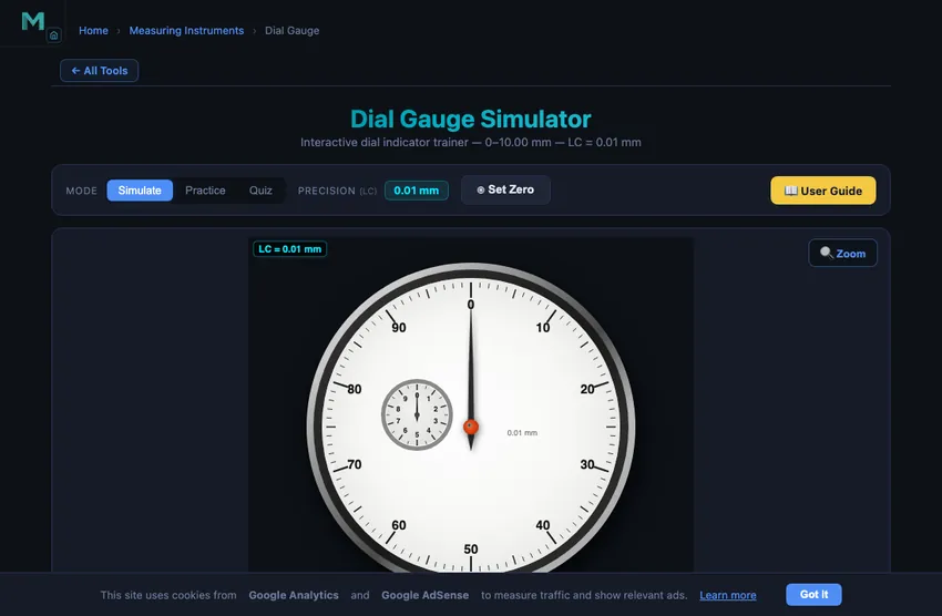
A dial gauge (also called a dial indicator or dial test indicator) is a precision instrument used to measure small linear displacements, runout, flatness, and parallelism in machining, quality control, and precision engineering. This free online simulator covers 0–10.00 mm with a 0.01 mm least count, including a revolution-counter sub-dial.
How to Read a Dial Gauge — Step by Step
A dial gauge has two scales: (1) Main dial with 100 divisions, each = 0.01 mm — one full revolution = 1 mm. (2) Revolution counter sub-dial showing complete revolutions (whole millimetres). To read: note the sub-dial value in whole mm, then add the main dial reading. Example: sub-dial = 3, main dial = 47 → reading = 3.47 mm.
Dial Gauge Specifications at a Glance
| Parameter | Typical Value | Notes |
|---|---|---|
| Least count (resolution) | 0.01 mm | 0.001 mm on high-precision models |
| Main dial divisions | 100 | One full revolution = 1.00 mm |
| Measuring range | 0–10 mm | Plunger types up to 25–50 mm |
| Revolution counter | 0–9 (whole mm) | Counts complete needle turns |
| Typical accuracy | ±0.01 mm | Per ISO 463 / ASME B89.1.10M |
| TIR (runout) | Max − Min | Equals 2 × shaft eccentricity |
How to Zero a Dial Indicator — What Actually Moves
Before taking measurements a dial gauge must be pre-loaded and zeroed against a reference surface. The step people get wrong is what zeroing does. You do not wind the instrument back to nought — that would lift the contact tip off the work and destroy the setup you just made. You turn the bezel. The dial plate rotates under a needle that does not move, until the printed 0 comes under the needle tip.
Which is why, on a correctly zeroed gauge, the printed zero is usually not at twelve o'clock. It is wherever the needle was standing when you set the datum. A student who has only seen pictures of a dial indicator at rest finds that alarming; it is the normal working state of the instrument.
This simulator zeroes the way the instrument does — press X or the ⊛ ZERO button and you can watch the plate turn while the needle holds station, pre-load intact. ↺ RESET (or R) puts it back: zero cleared, plunger let down onto its datum, both needles travelling home with it.
The Bezel Clamp — and Why Every Indicator Has One
A bezel free to turn is a datum waiting to be lost. Knock the gauge, or brush the rim while repositioning a part, and the zero moves — and a wrong datum looks exactly like a right one, so every part measured afterwards is out by the same amount and nothing on the face says so. That is what the bezel clamp is for: the short knurled tab on the rim, pushed in to pinch the bezel against the case. Set the zero, lock the bezel, then start measuring. In this simulator the tab sits down flush when locked, and Set Zero then refuses out loud instead of quietly moving your datum.
Datum + Reading = Size: Using a Dial Gauge as a Comparator
A dial indicator is a comparator. It is very good at telling you how far one thing differs from another and, on its own, poor at telling you how big something is — its range is short and its zero is wherever you last put it. The working method closes that gap with arithmetic:
- Wring a stack of known size under the plunger. That is the datum — a length you already trust, to a class of accuracy the indicator itself cannot reach.
- Zero on it, and lock the bezel.
- Swap the part in. The dial now reads the deviation, with a sign: over or under.
- Add it back: datum + reading = the part's actual size.
That fourth step is the measurement. A deviation on its own is half of one, which is why this simulator prints the whole sum rather than the difference alone: once a zero is set, the reading breakdown stops counting revolutions and reads Zeroed on 1.16 mm → Divisions over 8 × 0.01 mm = 0.08 mm, a third reading cell shows the ACTUAL size, and the conversion card states it outright — Actual = datum 1.16 + reading 0.08 = 1.24 mm. This is how a bench comparator, a bore gauge and a height-setting micrometer are all used, and it is the reason a 0–10 mm indicator can measure a 40 mm part to a hundredth.
Tolerance Markers and Go/No-Go Inspection
Setting a pair of tolerance markers either side of zero turns the indicator from something you read into something you glance at. On an inspection bench checking a batch, that is the difference between a part every few seconds and a part every few seconds plus a chance to misread a decimal. The needle sits inside the markers or it does not.
Because the markers are carried on the dial plate they ride with the bezel, so zeroing takes the whole accepted band to the new datum — set the tolerance once and it follows every datum you set afterwards. In this simulator the pointers move in whole graduations, so the band is always a number the fitted instrument can actually show: ±0.02 mm is ±2 divisions on a 0.01 mm gauge, and ±.002″ is ±2 divisions on a .001″ one. They stop at half a revolution, past which a marker has wrapped round the face and no longer marks a limit. Real markers are friction-set and will sit anywhere; snapping them to a line is the one deliberate difference here, because ±0.0173 mm is not a tolerance anyone sets on a dial graduated in hundredths.
Dial Gauge Applications in Engineering
- Checking shaft runout and eccentricity on a lathe or grinder
- Measuring surface flatness and parallelism on a surface plate
- Setting up milling machine vices and fixtures
- Verifying bore diameter with a bore gauge attachment
- Slip gauge (gauge block) calibration — included in this simulator's practice mode
The Two Uses Every Machinist Knows
Dial gauges live mostly in two situations, and a working machinist reaches for one a dozen times a day.
First, runout checking. Mount the gauge so its contact tip touches a rotating shaft. Spin the shaft slowly. The dial needle traces the eccentricity — total indicated runout (TIR) is the difference between maximum and minimum readings. A precision-ground shaft should show under 0.01 mm TIR; anything over 0.05 mm means bent, worn, or improperly chucked. The same technique checks lathe chuck runout, milling spindle runout, and bearing journal concentricity.
Second, parallelism on a surface plate. Mount the gauge on a height-gauge column. Slide it across a surface that should be parallel to the plate. Variation in the dial reading shows the angular deviation. ISO 286 tolerance grades for machined surfaces typically allow 0.01−0.02 mm of flatness per 100 mm; the dial gauge catches deviations a quarter of that.
Lever-Type vs Plunger-Type — Two Different Tools
The instrument in this simulator is the plunger-type dial indicator. Its sibling is the lever-type dial test indicator (DTI), with a hinged contact arm rather than an in-line spindle. Both achieve about the same precision but suit different geometries:
- Plunger type. Long travel (10−25 mm). Direct push-in reading. Best for slow-moving displacements: surface plate work, gauge-block stacks, simple runout checks where the contact direction stays normal to the surface.
- Lever (test) type. Short travel (about 0.8 mm). Hinged tip can sweep into tight features — cylinder bores, inside corners of fixtures, between gear teeth. The standard tool for setting up a milling vice parallel to the X-axis: sweep the DTI across the jaw and adjust until the reading stays constant.
Reading an Inch Dial Indicator (AGD)
Switch the simulator to Imperial and you are not handed the metric face with inch labels — you are handed a different instrument, because an inch dial indicator genuinely is one. Two differences a unit conversion cannot produce:
- One revolution is .100″, not 1 mm. A .001″ indicator carries 100 divisions, so a full sweep of the needle is one tenth of an inch and the revolution counter reads tenths of an inch. Converting the metric face would give 1 mm per revolution, which is not a dial anyone manufactures.
- Balanced dials. Inch tolerances are usually quoted both ways (±.002″), so shop indicators are often balanced — numbered outward from zero in both directions — where a long-range metric gauge is continuous.
The balanced gauge in this simulator is modelled on a real instrument, the Starrett 25-131J: .0005″ graduation, 0-25-0 dial, .050″ per revolution, 0–.125″ range. Note what its numerals mean. They are engraved in thousandths, not division counts, so the numeral 25 stands fifty graduations from zero (25 thou = .025″ = half a revolution). Reading it as “division 25” halves every measurement.
It also carries no revolution counter, and that is not an omission. A balanced dial is a comparison instrument: wound continuously it reads 0→25 down one side and back up the other, so the numeral alone is ambiguous by design. You do not measure a part from zero with it — you zero it on a reference and read how far the part sits over or under. That is why Practice and Quiz on that gauge wring up a reference stack, zero on it, and then ask for the deviation. Where a balanced indicator does have a small counter hand, it is a warning device rather than part of the reading.
Inch Gauge Blocks
Switching units swaps the drawer rather than converting it, because a US shop owns different steel — and calls it by a different name. Metric mode stocks the standard 47-piece slip gauge set to ISO 3650; Imperial mode stocks the classic 81-piece gage block set (ASME B89.1.9 is titled Gage Blocks, and that spelling is the US convention): .1001–.1009″ in ten-thousandths, .101–.149″ in thousandths, .050–.950″ in fiftieths, and the 1, 2, 3 and 4″ long blocks. Only the blocks the fitted gauge can actually read are offered.
The ten-thousandths series carries the same lesson the metric 1.005 mm block does: wring on a .1001″ block and a .001″ dial reads .100″, because the needle lands between two lines. The instrument is not wrong — it simply cannot resolve a tenth of a thou, and knowing which instrument a tolerance demands is the point.
Calibration and Standards
- ISO 463:2006 — Geometrical product specifications (GPS) — Dimensional measuring equipment — Design and metrological characteristics of mechanical dial gauges.
- ASME B89.1.10M — Dial Indicators (For Linear Measurements).
- JIS B 7503 — the Japanese standard, often referenced for Mitutoyo instruments.
- ISO 3650:1998 / DIN EN ISO 3650 — Length standards — Gauge blocks. Simulate mode stocks the standard 47-piece metric set: the 1.005 mm block, the 1.01–1.20 hundredths series, the 1.3–1.9 tenths series, 1–9 mm whole millimetres, and 10–100 mm in tens (1 + 20 + 7 + 9 + 10 = 47). Only the blocks the fitted gauge can read are offered.
- ASME B89.1.9 — Gage Blocks. The US standard, and the reason Imperial mode calls them gage blocks rather than slip gauges: the two systems genuinely use different words for the steel, and neither is a translation of the other.
- Calibration interval. 6 to 12 months for shop-floor use, against a class-1 gauge-block set at five points across the range.
Explore Related Simulators
If you found this Dial Gauge simulator helpful, explore our Dial Caliper simulator, Height Gauge simulator, Vernier Caliper simulator, Micrometer Screw Gauge simulator, and Lathe Machine simulator for more hands-on practice.
Updated