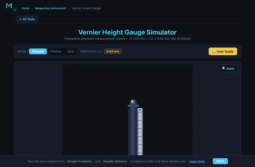
Vernier Height Gauge Simulator
Interactive precision measurement trainer — 0–120 mm — LC = 0.02 mm (50 divisions)
1 Overview
This vernier height gauge simulator is a free online tool for practising how to read a height gauge with 0.02 mm precision (50-division vernier scale). The height gauge is a precision measuring instrument mounted on a vertical column with a datum surface (base), used for measuring and scribing heights in toolrooms, quality control labs, and inspection departments. This simulator covers the 0–120 mm range and is designed for engineering students, engineering diploma candidates, and vocational trainees preparing for metrology assessments.
2 Setting the Zero

The simulator opens in Simulate mode with the carriage at a default height. To begin:
- Drag the sliding carriage up or down along the vertical column to set a height. The arrow keys move it one least count at a time, which is the finer control; Page Up and Page Down step a whole millimetre. The mouse wheel is left alone for scrolling the page.
- The info row below the canvas shows the MSR (Main Scale Reading), VSR (Vernier Scale Reading), LC (Least Count = 0.02 mm), and the full TR formula with live values.
- Use the Zoom button to magnify the vernier coincidence area on the vertical scale for accurate reading.
3 Taking a Reading
In Simulate mode the carriage slides freely on the column. The formula panel breaks down the reading: TR = MSR + (VSR × 0.02). The main scale is engraved on the vertical beam in 1 mm divisions, and the vernier scale on the sliding carriage has 50 divisions spanning 49 mm. When the nth vernier division aligns with a main scale graduation, the fractional part of the measurement is n × 0.02 mm. Use this mode to understand how height changes correspond to vernier coincidence shifts.
3b The 3D View
Press 3D in the View pills at the top right of the instrument. The flat view stays the default; the page remembers your choice on this device, and 2D takes you back. The 3D height gauge is the same instrument at true size: the same reading, the same grading and the same walkthrough as the flat view.
- Move it: drag the carriage up or down. Drag the knurled fine-feed nut between the two blocks for one least count at a time, or click its upper or lower half for a single step; a mouse-wheel notch over the nut does the same. The arrow keys work in both views. A face on the part stops the scriber, exactly as in 2D.
- Look round it: drag the background to orbit, right-drag or Shift-drag to pan, and pinch or Ctrl + scroll to zoom. A plain scroll moves the page. On a computer the cube at the top right turns the view to any face, edge or corner.
- Views: Whole (the gauge on its granite surface plate), Reading (square to the scales), Scriber (the carbide point on the face you are lowering onto) and Parallax, with an eye-angle slider showing how far the reading moves when your eye is above or below the vernier edge. Labels names the parts, and with a part loaded Close-up keeps the scriber in a corner view while you read the scales.
- Two-reading parts: on the step block the part slides on the plate so the face you are probing is under the scriber, the way you would slide the gauge, and it only moves once the scriber is clear above it.
In Practice and Quiz the 3D view shows no reading, no gold coincidence line and no parallax figure until your answer has been marked. The green contact line still shows, because touching the face is not the answer. If your browser cannot run WebGL, the 3D pill is disabled and the flat view carries on.
4 Practice & Quiz
Practice mode: A random height is set and the carriage is locked. Read the main scale and vernier scale, then type the total reading into the input box. Click Check for instant feedback showing whether your answer is correct. Click New for another random height. Your running score is displayed.
Quiz mode: A timed series of 5 questions tests your height gauge reading accuracy under exam conditions. After completing all questions, a results panel shows your score, star rating, and a question-by-question breakdown with the correct answers.
5 Understanding the Reading
The height gauge reading follows the same vernier principle as a vernier caliper:
- MSR (Main Scale Reading): The last whole millimetre mark below the vernier zero on the vertical beam.
- VSR (Vernier Scale Reading): The vernier division (0–49) that coincides exactly with any main scale line.
- LC (Least Count): 0.02 mm for a 50-division vernier scale.
Total Reading = MSR + (VSR × 0.02). Example: MSR = 47 mm, VSR = 18 → TR = 47 + (18 × 0.02) = 47.36 mm.
6 Workshop Tips
- Always place the height gauge on a clean, flat surface plate (datum surface) — any debris under the base introduces height errors.
- Use the fine adjustment knob to make micro-adjustments before locking the carriage — this ensures the scriber tip touches the workpiece without excess pressure.
- Check for zero error by lowering the scriber to the surface plate and confirming the reading is exactly 0.00 mm before measuring.
- When scribing layout lines, ensure the workpiece is properly degreased so the scribed line is clearly visible.
How to Read a Vernier Height Gauge — Online Practice Simulator
A Vernier height gauge is a precision measuring instrument used to measure the height of a workpiece from a reference surface (usually a surface plate or granite table). With a 0.02 mm least count and a 50-division vernier scale, this instrument is widely used in quality control, toolroom work, and precision engineering training.
Vernier Height Gauge Specifications
The least count of a vernier height gauge is 0.02 mm — one main-scale division (1 mm) divided by the 50 vernier divisions, i.e. 1/50 mm. Every reading is built the same way, on every scale: TR = MSR + (VSR × LC).
Four instruments are on the bench above — two metric and two US-customary — and they are genuinely different gauges, not one gauge with its numbers converted. Switch between them with the Units and Gauge controls; the beam, the vernier, the numbering, the readout and the answer box all change together.
| Gauge | Main scale | Vernier | Least count | Range | Vernier numbering |
|---|---|---|---|---|---|
| Metric, fine | 1 mm | 50 div / 49 mm | 0.02 mm | 0–120 mm | 0 1 2 … 9 0 (tenths of a mm) |
| Metric, coarse | 1 mm | 20 div / 39 mm | 0.05 mm | 0–120 mm | 0 1 2 … 9 0 (tenths of a mm) |
| Decimal inch | 0.025 in (40ths) | 25 div / 0.600 in | 0.001 in | 0–6 in | 0 5 10 15 20 25 (by division) |
| Fractional inch | 1/16 in | 8 div / 7/16 in | 1/128 in | 0–6 in | 0 2 4 6 8 (by division) |
A 20-division metric gauge reads to 0.05 mm; dial and digital height gauges typically read to 0.01 mm. The US-customary gauges are the same instrument with the beam divided differently: the decimal one is graduated in fortieths (0.025 in) and read against a 25-division vernier for 0.001 in, while the fractional one is graduated in sixteenths and read against an 8-division vernier for 1/128 in — and is read in fractions, never decimals.
Guided Reading — “Show me How?”
Reading a vernier is a skill of the eye, and a static diagram cannot teach it. Press Show me How? — the round play button at the top-right of the gauge, under the Zoom and object buttons — and the simulator takes the reading currently on the instrument and works through it on the metal itself, one step at a time. Nothing is read off a side panel: the arrows, the rejected lines and the running count are drawn on the scales you are being taught to read, and the camera moves in to hold both ends of the reading at once.
- Main Scale Reading — a line grows up the column to the vernier zero, and an arrow names the last main-scale graduation below it.
- Find the coinciding line — the scan works up the vernier, marking each line that misses, and carries on one division past the match so you can see the fit is unique rather than merely the first one tried.
- Count the divisions — counted the way a fitter counts, on from the nearest numbered line rather than one at a time from zero, with the running VSR × LC building beside it.
- Total Reading — the arithmetic, with both ends of the reading still on screen.
Use ‹ and › (or the arrow keys) to step through it at your own pace, Space to pause, Esc to close. It is hidden in Quiz mode, and in Practice until your attempt has been marked — a step-by-step reading of the instrument is the answer you owe.
Step-by-Step: How to Read a Vernier Height Gauge
Step 1 — Place on surface plate: The height gauge base sits on a precision surface plate, providing the reference plane. Step 2 — Main Scale Reading (MSR): Read the last whole millimetre mark below the vernier zero line on the main scale. Step 3 — Vernier Scale Reading (VSR): Find which vernier graduation coincides with a main scale line. Count that division number. Step 4 — Total Reading (TR): Apply TR = MSR + (VSR × LC) where LC = 0.02 mm.
Example Reading
If the main scale shows 47 mm (MSR = 47) and the 18th vernier division aligns with a main scale line (VSR = 18), then: TR = 47 + (18 × 0.02) = 47 + 0.36 = 47.36 mm.
Vernier Height Gauge Parts and Functions
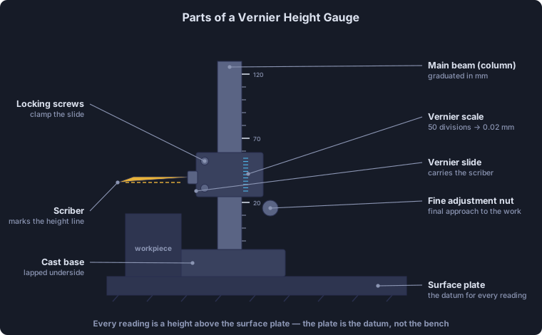
Key parts: base (sits on surface plate), vertical beam/column (carries the main scale), sliding carriage (carries the vernier scale and scriber arm), scriber/measuring jaw (the actual measuring tip), locking screw (clamps carriage at reading), and fine adjustment knob (for precise positioning).
50-Division Vernier — Why 0.02 mm?
The vernier scale has 50 divisions that span 49 main scale divisions. One vernier division = 49/50 mm = 0.98 mm. The difference between 1 main scale division (1 mm) and 1 vernier division (0.98 mm) = 0.02 mm — this is the least count. When the nth vernier division coincides with a main scale line, the measurement is MSR + n × 0.02 mm.
How the Vernier Scale Is Numbered — 0 1 2 … 9 0
Pick up a real metric height gauge and the vernier scale is not numbered 0, 10, 20, 30, 40, 50. It is numbered in tenths of a millimetre: 0 1 2 3 4 5 6 7 8 9 0. The numerals mark the value of a division, not its index — and because the whole vernier spans exactly one millimetre, the run closes back on 0 at the far end. That closing zero is the signature of a metric vernier.
Which divisions carry a numeral therefore depends on the least count:
- 0.02 mm (50 divisions) — a numeral every 5th division, since 5 × 0.02 = 0.1 mm.
- 0.05 mm (20 divisions) — a numeral every 2nd division, since 2 × 0.05 = 0.1 mm.
Why the 0.05 mm Vernier Is 39 mm Long, Not 19
The vernier every textbook draws is the ordinary form: n divisions spanning n − 1 main divisions. A 20-division 0.05 mm scale built that way spans just 19 mm — and next to a 50-division scale spanning 49 mm on the same instrument, it is a stub with its numerals crowded twice as close together.
Real coarse verniers are therefore cut in the extended or long form, spanning 2n − 1 main divisions:
20 divisions over 39 mm → 1 vernier division = 39/20 = 1.95 mm
LC = 2 MSD − 1 VSD = 2.00 − 1.95 = 0.05 mm
Same least count, twice the pitch. The reading method does not change either — the coinciding division still gives VSR directly — but the line it coincides with is now main-scale line MSR + 2 × VSR instead of MSR + VSR. (39 mm is as close to 49 as a 20-division scale can get: it is limited to 19, 39 or 59 mm.)
The 0.02 mm scale stays in the ordinary form, because a long-form version would span 99 mm and no longer fit a sensible carriage. The inch gauges keep the authentic short textbook vernier too. Switch between 0.02 mm and 0.05 mm above and watch the vernier plate change length while the least count changes with it.
So on the 0.02 mm gauge the numeral 3 sits on vernier division 15 and means 0.30 mm. To read a coincidence you find the nearest numeral and count divisions on from it: the 18th division is three past the numeral 3, so the fraction is 0.30 + 3 × 0.02 = 0.36 mm. Counting all the way from zero to 18 is what students do when a simulator engraves the index instead of the value — and it is not how the instrument is read at the bench.
The Decimal-Inch Height Gauge — Least Count 0.001 in
The US-customary gauge is the same instrument with a different division of the beam. Its main scale is graduated in fortieths of an inch (0.025 in), with a long numbered line at every inch and a medium line at every tenth. Its vernier carries 25 divisions spanning 24 main divisions (0.600 in), so the least count is 0.025 ÷ 25 = 0.001 in.
Unlike the metric scale, an inch vernier is genuinely numbered by division — 0, 5, 10, 15, 20, 25 — because each division is already a round 0.001 in and the numeral and the index coincide. A reading of MSR = 1.850 in with the 15th vernier division coinciding is 1.850 + 15 × 0.001 = 1.865 in. Switch the simulator to inch to work on this scale; the main beam, the vernier, the numbering and the answer box all change with it.
The Fractional Height Gauge — Least Count 1/128 in
Layout and scribing work — which is what a height gauge and its scriber are for — is still dimensioned in halves, quarters, eighths and sixteenths on a US shop drawing. So the same beam is re-engraved in sixteenths of an inch and read against an 8-division vernier spanning 7 main divisions (7/16 in):
LC = 1 MSD − 1 VSD = 1/16″ − 7/8 × 1/16″ = 1/16″ ÷ 8 = 1/128″
Worked example. The main scale shows 1‑5/16″ below the index and the 3rd vernier division coincides. Then TR = 1‑5/16 + 3/128 = 1‑40/128 + 3/128 = 1‑43/128″.
Read it as a fraction, never as a decimal — that is the whole point of the scale. The simulator shows the exact decimal equivalent beside the reading (1‑43/128″ is 0.3359375″ past the inch, exactly, because binary denominators terminate), because a fractional measurement is constantly compared against a decimal drawing. It never replaces the fraction with it.
Notice how the beam is graduated: the tick height steps down 1″ > 1/2″ > 1/4″ > 1/8″ > 1/16″, exactly as a steel rule is graduated, so sixteenths can be counted without reading a single number. Whole inches are numbered and the quarter points carry a small ¼ ½ ¾. That hierarchy, not the numerals, is what makes a 16ths scale readable at a glance.
Least Count of Vernier Height Gauges — and How It Compares
Least count is the smallest change an instrument can resolve. For a vernier height gauge it is set entirely by how the vernier scale is divided: one main-scale division divided by the number of vernier divisions. Vernier height gauges are most commonly 50-division, giving 0.02 mm.
| Instrument | Scale / divisions | Least count | How it is derived |
|---|---|---|---|
| Vernier height gauge | 50 divisions | 0.02 mm | 1 mm ÷ 50 |
| Vernier height gauge (coarse, long form) | 20 divisions / 39 mm | 0.05 mm | 2 mm − 1.95 mm |
| Vernier height gauge (decimal inch) | 25 divisions | 0.001 in | 0.025 in ÷ 25 |
| Vernier height gauge (fractional inch) | 8 divisions | 1/128 in | 1/16 in ÷ 8 |
| Dial height gauge | dial indicator | 0.01 mm | set by the indicator |
| Digital height gauge | electronic encoder | 0.01 mm | encoder resolution |
| Vernier caliper | 50 divisions | 0.02 mm | 1 mm ÷ 50 |
| Micrometer (screw gauge) | 50 divisions | 0.01 mm | 0.5 mm pitch ÷ 50 |
In inch units a vernier height gauge is usually divided to 0.001 in; the fractional layout scale reads to 1/128 in, which is 0.0078125 in — coarser than the decimal gauge, and deliberately so, because the drawing it is working from is dimensioned in sixteenths. Note that least count is not the same as accuracy — it is the finest division you can read, while accuracy also depends on the surface plate, the squareness of the column, parallax and the operator’s feel for scriber contact. A gauge reading to 0.02 mm may still be several hundredths out if it is used on a worn plate.
Vernier Height Gauge 3D Simulation — on a Granite Surface Plate
Press 3D in the View pills at the top right of the instrument (the page opens in the flat view) and the height gauge becomes an operable 3D model at true size, free in the browser with no download. It stands on a black granite surface plate: a flat-blade column with its graduated band, the slide arm with its bevelled vernier plate, the fine-adjustment block with a knurled feed nut, two locking screws, and a cranked scriber with a carbide point. The reading, the grading and the “Show me How?” walkthrough are the same as in the flat view, and the scales are engraved by the same rules, so the 0.02 mm, 0.05 mm, 0.001 in and 1/128 in verniers read identically in both.
Drag the carriage up or down, or turn the fine-feed nut one least count at a time, and the scriber stops on the face you are lowering onto. The Parallax view has an eye-angle slider that shows how far the reading moves when your eye is above or below the vernier edge, which is why a vernier is read square-on. On the step block the part slides on the plate so the face being probed sits under the scriber, the way you would slide the gauge in an inspection room. In Practice and Quiz the 3D view shows no reading until your answer has been marked.
The same 3D treatment is available for the vernier caliper, the micrometer screw gauge and the dial caliper.
Applications of the Vernier Height Gauge
- Measuring the height of machined components from a datum surface
- Scribing layout lines at precise heights on workpieces
- Checking step heights and shoulder lengths on turned parts
- Verifying parallelism of surfaces on a surface plate
- Setting cutting tool heights on lathes and milling machines
Why the Surface Plate Is Half the Tool
A height gauge is useless without a precision surface plate underneath it. The plate is the reference datum from which every height is measured. Workshop-grade granite plates (the standard) are flat to about 5 µm per 600 mm; inspection-grade plates are flat to 1 µm per 600 mm. The plate’s mass (typically 50−200 kg) keeps it vibration-free; its hardness keeps it from wearing under repeated tool contact; its low coefficient of thermal expansion keeps the reference stable through temperature variations that would distort a steel plate.
Cast iron plates were the historical standard from the 1850s to about 1960. Granite displaced them because it doesn’t corrode, doesn’t pick up burrs from contact wear, and resists thermal cycling better. Most modern toolrooms have both: cast iron for rough work, granite for inspection.
Layout Work — What the Scriber Is For
The scriber tip on a height gauge is not primarily a measuring jaw. It is a marking tool. The classic workflow:
- Coat the workpiece with layout dye (typically a blue alcohol-based marking fluid).
- Reference the height gauge to a known datum — usually a face of the workpiece, set up so it sits parallel to the surface plate.
- Set the carriage to the first layout dimension (say 25.00 mm), lock it, and draw the scriber across the workpiece face. A fine scratched line appears in the dye at exactly that height.
- Reset the carriage to the next dimension and repeat. Hole centres, edge boundaries, machined-surface boundaries all get scratched in.
- The machinist follows the scribed lines with mill or drill for the first-cut work, then dial-indicates for final precision.
This sequence has not changed since the 1900s. CNC machining has reduced the need for layout work, but on one-off parts, prototype tooling, and repair work, a height gauge plus surface plate plus scribe is still the fastest way to lay out hole patterns and machined boundaries.
Standards and Calibration
- ISO 13225:2012 — Geometrical product specifications (GPS) — Dimensional measuring equipment — Design and metrological characteristics of mechanical height gauges.
- BS 1643 — the British Standard for precision height gauges.
- DIN 866 / DIN 876 — standards for granite surface plates, with class 00, 0, 1, 2 designations covering flatness from 1 to 10 µm per metre.
Explore Related Simulators
If you found this Height Gauge simulator helpful, explore our Vernier Caliper simulator, Dial Gauge simulator, and Micrometer Screw Gauge simulator for more hands-on practice. The micrometer also runs in 3D: open the Screw Gauge 3D simulation to turn the thimble by hand and cut the sleeve open to see the screw thread that sets its 0.01 mm least count.
Updated