Lathe Machine Simulator
Parts Identification • Turning, Facing, Threading • Cutting Parameters — Simulate • Explore • Practice • Quiz
| # | Question | Result |
|---|
1 Overview
The Lathe Machine Simulator is a virtual centre lathe that lets you perform turning, facing, boring, threading, and taper turning operations on different materials. The lathe is called the "mother of all machines" because of its versatility in producing cylindrical surfaces. This simulator teaches you how each lathe component works, how to set cutting parameters, and how those parameters affect material removal rate, cutting force, power consumption, surface roughness, and machining time.
The simulator supports multiple operations and materials, with real-time calculation of cutting speed (V = pi D N / 1000), feed rate, depth of cut, MRR, power, cutting force, surface roughness, and machining time. The dual-canvas layout shows the lathe machine with animated workpiece rotation and chip removal on the left, and cutting parameter diagrams on the right.
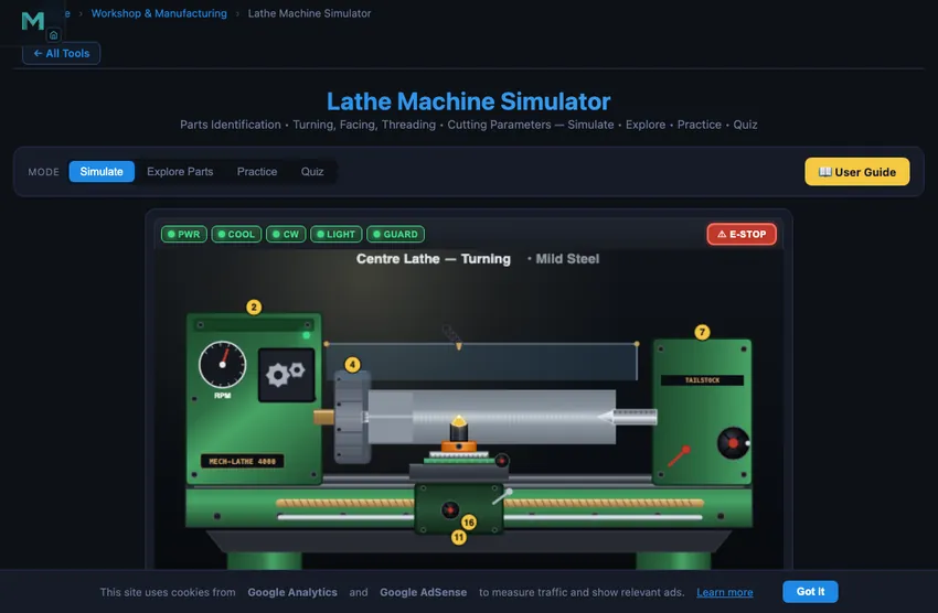
2 Setting Up the Job

The simulator opens in Simulate mode. The left canvas shows the lathe machine with all major parts labeled. The right canvas displays cutting diagrams and parameter graphs with badges showing cutting speed, RPM, feed rate, and power. The control panel below provides operation selection (turning, facing, threading, etc.), material selection, and sliders for spindle speed, feed rate, depth of cut, and workpiece diameter.
To perform your first operation: (1) Select an operation (e.g., Turning). (2) Choose a material. (3) Set the spindle speed, feed rate, depth of cut, and workpiece diameter using the sliders. (4) Click "Start Machining" to begin the operation. Watch the workpiece rotate, the tool advance along the surface, and chips being removed. The readout grid updates with all eight calculated parameters. Click "Reset" to prepare for a new operation.
3 Running the Operation
In Simulate mode, the left canvas animates the lathe operation. For turning, you see the workpiece spinning in the chuck while the cutting tool feeds along its length, reducing the diameter. For facing, the tool moves radially across the end face. For threading, the carriage engages the lead screw to cut helical grooves at the correct pitch. The animation shows realistic chip formation and surface generation.
The readout grid shows eight results: Cutting Speed (m/min), Feed Rate (mm/rev), Depth of Cut (mm), MRR (mm^3/min), Power Required (kW), Cutting Force (N), Surface Roughness (micrometers Ra), and Machining Time (seconds). Experiment with different parameter combinations to see how increasing feed rate improves productivity but worsens surface finish, or how depth of cut affects power requirements.
4 Speeds, Feeds & Theory
The Explore Parts mode provides an interactive identification guide to all major lathe components. Categories cover the headstock assembly (spindle, chuck, gearbox), tailstock, bed and ways, carriage (cross-slide, compound rest, tool post), apron (feed mechanism, half-nut), and the lead screw. Click any part to highlight it on the canvas diagram and read its description, function, and specifications.
Additional topics cover lathe specifications (swing over bed, distance between centers, spindle bore), types of lathes (engine lathe, turret lathe, CNC lathe), tool geometry (rake angle, clearance angle, nose radius), and cutting fluid functions. This reference library is essential for understanding how each part contributes to the machining process.
5 Try a Problem
Practice mode generates calculation problems about lathe operations. Typical problems ask you to calculate spindle RPM from cutting speed and diameter, determine MRR for given parameters, find machining time for a given length and feed rate, or compute the power required for a turning operation. Enter your answer and check it with step-by-step solutions available.
Quiz mode presents five questions per session covering both parts identification (name the component shown) and numerical calculations. Topics include cutting speed formula, feed rate selection, MRR calculation, power estimation, and surface roughness prediction. Review your results and retake the quiz to master lathe machine fundamentals.
6 Shop Tips
- Master the fundamental formula V = pi D N / 1000 first, as it connects cutting speed, diameter, and RPM for all lathe calculations.
- Remember that MRR in turning equals pi D d f N / 1000, where d is depth of cut and f is feed per revolution.
- Use Explore Parts mode to learn all components before attempting the quiz, as parts identification questions are common.
- When increasing depth of cut, watch how power requirement and cutting force increase proportionally.
- Surface roughness improves (lower Ra) with smaller feed rate and larger tool nose radius. The formula is Ra = f^2 / (32 r).
- For threading operations, the feed rate equals the thread pitch, and the carriage must be driven by the lead screw to maintain accurate pitch.
- Compare different materials at the same cutting parameters to see how harder materials require more power and produce higher cutting forces.
What is a Lathe Machine?
The lathe is the most versatile and widely used machine tool, often called the "mother of all machines." It produces cylindrical surfaces by rotating the workpiece against a stationary cutting tool. The main components include headstock (with spindle and chuck), tailstock (for support), bed (precision-ground ways), carriage (with cross-slide, compound rest, and tool post), and the apron (with feed mechanism and lead screw engagement).
This simulator lets you identify all major parts of a centre lathe, perform turning, facing, threading, boring, and taper turning operations, and calculate cutting speed (V = πDN/1000), material removal rate, power consumption, cutting force, and surface finish in real time.
Lathe Operations
Primary operations include: Turning (reducing diameter), Facing (machining end surface), Boring (enlarging internal diameter), Threading (cutting screw threads), Taper Turning (producing conical surfaces), Knurling (creating textured grip patterns), and Parting/Cut-off (separating finished parts). Each requires different tool geometry, speed, and feed settings.
Lathe Specifications
A lathe is specified by: Swing over bed (max workpiece diameter), Distance between centers (max workpiece length), Spindle bore diameter, Range of spindle speeds (RPM), Number of feeds available, Motor power (HP/kW), and Bed length. Understanding these specifications helps in selecting the right lathe for a given job.
Picking Speed and Feed — A Worked Mild-Steel Job
You are turning a 50 mm diameter mild steel bar with a HSS tool. The handbook says cutting speed for mild steel with HSS is 25−30 m/min. Pick V = 28 m/min. What spindle RPM do you set?
| Step | Working | Result |
|---|---|---|
| Apply cutting speed formula | V = πDN/1000 | — |
| Rearrange for N | N = 1000V/(πD) = 1000×28/(π×50) | N = 178 RPM |
| Round to nearest available gear | typical lathe steps: 80, 125, 180, 250 RPM | Use 180 RPM |
| Actual cutting speed at 180 RPM | V = π×50×180/1000 | 28.3 m/min ✓ |
| Feed for finish pass on mild steel with HSS | recommended 0.1−0.2 mm/rev | 0.15 mm/rev |
| Material removal rate (per pass, 0.5 mm depth) | MRR = V × f × d × 1000 | 2125 mm³/min |
Three rules of thumb that come straight from the workshop:
- HSS tools cut at one third the speed of carbide. If you switch from HSS to a carbide insert, multiply your RPM by about three. The carbide can take the heat.
- Smaller diameter, higher RPM. As you turn down a long taper, the diameter drops. Strictly the RPM should rise to maintain constant V. Modern CNC lathes do this automatically (constant surface speed mode, G96); on manual lathes you change gear occasionally.
- Slow down for threading. Threading cuts at roughly one quarter the turning speed for the same material, because the chip is much wider relative to the depth of cut.
Workshop Safety — Five Things My Old Instructor Made Us Repeat
- Stop the spindle before measuring. A vernier caliper on a rotating workpiece can fly out and hit you, or worse, drag your hand in.
- Remove the chuck key. Every chuck key has a return spring. If you leave it in and the spindle starts, it becomes a missile. The number of workshop ceilings with chuck-key dents is shocking.
- Tie back hair, no jewellery, no loose sleeves. Anything that can wrap around a rotating workpiece will. A wedding ring caught in a chuck once cost a colleague a finger.
- Cutting tool sharp, not blunt. A blunt tool generates more heat and force; it wears faster and produces a worse finish. Re-grind regularly.
- Watch the chip colour. Light blue chips from steel mean the cut is right. Dark blue or black means the tool is overheating; reduce speed or add coolant. Silver is too cool; you can push harder.
References for Lathe Work
- Krar, S. F., Gill, A. R. & Smid, P. — Technology of Machine Tools, 8th ed., McGraw-Hill. The North American workshop reference.
- Sharma, P. C. — A Textbook of Production Engineering, 14th ed., S. Chand. Widely used in Indian polytechnics.
- Sandvik Coromant — Modern Metal Cutting. The industrial reference for cutting-speed and feed data, freely available online.
- BS 5050:1973 — Specification for centre lathes for general purposes. The British Standard still cited in engineering education.
Explore Related Simulators
If you found this Lathe Machine simulator helpful, explore our Milling Machine simulator, Drilling Machine simulator, Thread Nomenclature trainer, and Vernier Caliper simulator for more hands-on practice.