Milling Machine Simulator
Cutting Speed • Feed per Tooth • MRR • Power • Surface Finish — Simulate • Explore • Practice • Quiz
1 Overview
The Milling Machine Simulator lets you perform virtual milling operations with three cutter types (end mill, face mill, slot drill) on three workpiece materials (aluminum, mild steel, cast iron). Unlike a lathe where the workpiece rotates, in milling the multi-point cutting tool rotates while the workpiece is fed against it. This simulator calculates cutting speed, feed per tooth, material removal rate (MRR), power consumption, surface finish, and chip thickness in real time as you adjust parameters.
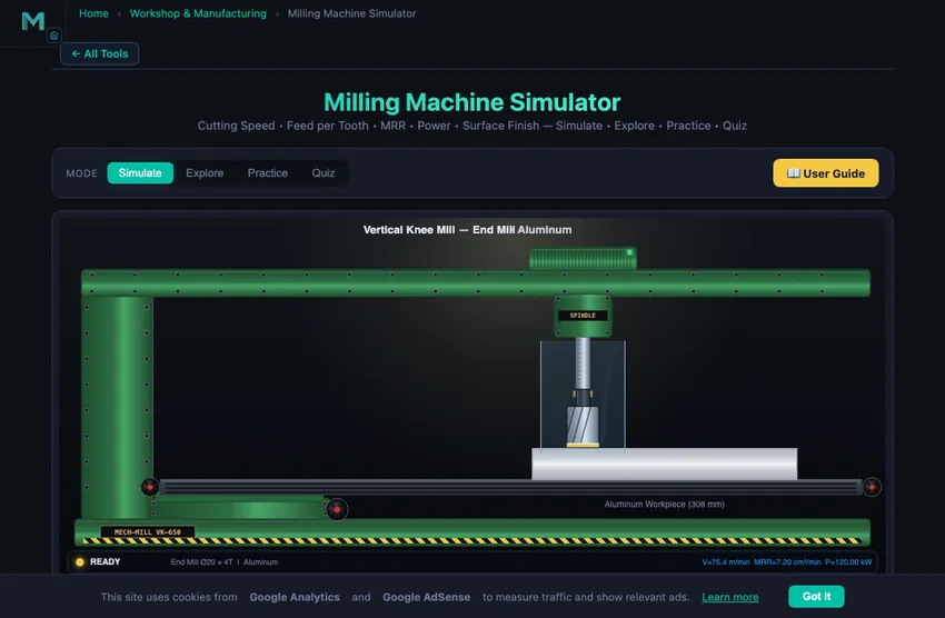
The interactive canvas shows a top-down view of the milling operation with animated cutter rotation and chip formation. Below, a readout row displays six key machining parameters. By adjusting spindle speed, feed rate, depth of cut, cutter diameter, and number of teeth, you can explore the relationships between these parameters and develop an intuitive understanding of milling process optimization.
2 Setting Up the Job

The simulator opens in Simulate mode with the canvas and control panel visible. The control panel has pill tabs for cutter type (End Mill, Face Mill, Slot Drill) and material (Aluminum, Mild Steel, Cast Iron), plus sliders for Spindle Speed (RPM), Feed Rate (mm/min), Depth of Cut (mm), Cutter Diameter (mm), and Number of Teeth. Action buttons let you start milling and reset.
To begin: (1) Select a cutter type (e.g., End Mill). (2) Choose a material (e.g., Mild Steel). (3) Set the spindle speed, feed rate, depth of cut, cutter diameter, and number of teeth using the sliders. (4) Click "Start Milling" to animate the cutting process. (5) Read the six calculated values in the readout row: Cutting Speed, Feed per Tooth, MRR, Power Required, Surface Finish, and Chip Thickness. Adjust sliders while running to see how parameters change in real time.
3 Running the Operation
The canvas animates the milling operation from a top-down perspective, showing the rotating cutter engaging the workpiece. Chip load visualization helps you see whether the current feed per tooth is within the recommended range. The cutter rotation speed scales with the spindle RPM setting, giving a visual sense of how fast the tool is turning.
The readout row shows: Cutting Speed (m/min) = pi D N / 1000, Feed per Tooth (mm/tooth) = Vf / (N x z), MRR (cm^3/min) = ap x ae x Vf / 1000, Power Required (kW), Surface Finish (micrometers Ra), and Chip Thickness (mm). Notice how increasing feed rate improves MRR but worsens surface finish, or how switching from aluminum to steel dramatically increases the power requirement at the same MRR. These trade-offs are the foundation of machining process planning.
4 Speeds, Feeds & Theory
Click the Explore tab to access a concept library organized into three categories: Fundamentals, Cutter Types, and Operations. Each category presents selectable concept cards. Click a card to view a detailed explanation with formulas, units, and worked examples in the info panel.
Topics include cutting speed calculation, feed per tooth optimization, MRR formula, power estimation using specific cutting force, climb vs. conventional milling, end mill geometry, face mill setup, slot drill characteristics, and surface finish prediction. This reference is invaluable for understanding the theory behind the numbers you see in Simulate mode.
5 Try a Problem
Practice mode generates random milling calculation problems. You might need to calculate the RPM for a desired cutting speed and cutter diameter, find the table feed rate from feed per tooth, RPM, and number of flutes, or determine the power required for a given MRR. Enter your answer and check it. Click "Show Solution" for a detailed step-by-step walkthrough.
Quiz mode tests your knowledge with five questions per session covering both theory (when to use climb vs. conventional milling) and calculations (compute MRR given specific parameters). Score 4 or more to confirm your understanding. Retake as needed, with new questions generated each time.
6 Shop Tips
- Start with the cutting speed formula V = pi D N / 1000 and its rearrangement N = 1000 V / (pi D) to calculate RPM from recommended cutting speed.
- Feed per tooth is the single most important parameter for tool life and surface quality. Keep it within recommended ranges: 0.05-0.2 mm/tooth for end mills in steel.
- Face mills have more teeth than end mills, so they achieve higher table feed rates at the same feed per tooth and RPM.
- Slot drills (2-flute) can plunge-cut, making them essential for pocket machining. End mills (4+ flutes) cannot plunge but give better surface finish.
- MRR is directly proportional to productivity. To increase MRR, increase depth of cut, width of cut, or feed rate, but check that power requirements stay within machine capacity.
- Aluminum allows 3-5x higher cutting speeds than steel, which is why it machines much faster with less power.
- In Practice mode, write the formula first, then substitute values. This builds exam readiness and reduces calculation errors.
Understanding Milling Machines — Free Interactive Simulator
A milling machine is one of the most versatile machine tools in any workshop, capable of producing flat surfaces, slots, pockets, gears, and complex 3D profiles. Unlike a lathe where the workpiece rotates, in milling the multi-point cutting tool rotates while the workpiece is fed against it. Our interactive milling machine simulator lets you explore how spindle speed, feed rate, depth of cut, and cutter geometry affect cutting speed, material removal rate, power consumption, and surface finish in real time. Adjust parameters for three cutter types — end mill, face mill, and slot drill — across aluminum, steel, and cast iron workpieces.
Cutting Speed and Feed Calculations in Milling
The cutting speed in milling is the peripheral velocity of the cutter, calculated as V = πDN / 1000 (m/min), where D is the cutter diameter in mm and N is the spindle speed in RPM. The feed per tooth (fz) determines how much material each tooth removes per revolution: fz = Vf / (N × z), where Vf is the table feed rate in mm/min and z is the number of teeth. Proper feed per tooth selection is critical — too low causes rubbing and work hardening, too high leads to excessive tool wear and poor surface finish. Typical fz values range from 0.05–0.2 mm/tooth for end mills in steel.
Material Removal Rate and Power
The material removal rate (MRR) in milling is calculated as MRR = ap × ae × Vf, where ap is the axial depth of cut, ae is the radial width of cut, and Vf is the feed rate. MRR directly determines the machining time and productivity. The power required depends on MRR and the specific cutting force (kc) of the material: P = MRR × kc / (60 × 1000 × η). Specific cutting forces vary significantly — approximately 800 N/mm² for aluminum, 2500 N/mm² for mild steel, and 1500 N/mm² for cast iron.
Milling Operations and Cutter Types
Face milling uses a large-diameter cutter to machine flat surfaces, with the cutter axis perpendicular to the machined surface. Peripheral (slab) milling cuts with the cutter periphery, producing surfaces parallel to the cutter axis. End milling combines both face and peripheral cutting for slots, pockets, and profiles. Slot milling uses a slot drill (typically 2-flute) to plunge into the workpiece and cut full-width slots. Each operation requires different speed, feed, and depth of cut parameters for optimal results.
Speed, Feed and Depth for an 8 mm End Mill in Mild Steel
The everyday milling calculation. You are slot-cutting mild steel with a 4-flute 8 mm carbide end mill. Pick parameters:
| Step | Working | Result |
|---|---|---|
| Cutting speed (Sandvik handbook for mild steel + carbide) | Vc = 120 m/min (mid-range) | — |
| Spindle RPM | N = 1000×Vc/(πD) = 1000×120/(π×8) | N = 4775 rpm |
| Round to nearest available step (typical mill) | 4500 or 5000 rpm | 5000 rpm |
| Recommended feed per tooth (handbook) | fz = 0.05 mm/tooth for slotting | — |
| Table feed rate | Vf = N × z × fz = 5000 × 4 × 0.05 | 1000 mm/min |
| Axial depth (slot full diameter) | ap = 8 mm (full diameter) | — |
| Material removal rate | MRR = 8 × 8 × 1000 | 64,000 mm³/min |
| Power required (kc = 2500 N/mm²) | P = MRR × kc/(60,000 × 0.85) | ~3.1 kW |
A modest 3.5−5 kW spindle handles this easily. With coolant the same setup runs all day. The simulator’s power-consumption readout flashes red if you exceed the assumed spindle power, which is the cue to drop either speed or depth of cut.
Climb vs Conventional — Which Way Does the Cutter Spin?
This is the topic every machinist has an opinion about. The two approaches differ in how the cutter and workpiece move relative to each other:
- Conventional milling (up milling). The cutter rotates against the direction of feed. Each tooth starts with zero chip thickness and grows to maximum at the exit. Tool wears uniformly. Tendency to lift the workpiece off the table — problematic for thin parts. Standard practice on older manual mills without backlash compensation.
- Climb milling (down milling). The cutter rotates in the direction of feed. Each tooth enters at maximum chip thickness and exits at zero. Better surface finish, longer tool life, downward force pushes the workpiece onto the table. Risky on backlash-prone manual mills because the cutter tries to “climb” into the cut.
Modern CNC machines with preloaded ball-screws and minimal backlash use climb milling almost exclusively. The simulator’s direction toggle lets students compare chip-thickness diagrams side by side. On a manual mill with backlash, conventional remains the safer choice; on a tight CNC, climb is the productivity choice.
The Five Cutter Types and When Each Earns Its Keep
| Cutter | Best for | Typical detail |
|---|---|---|
| End mill (4-flute) | Slots, profiles, pocketing | Most-used cutter; balanced chip clearance and rigidity |
| End mill (2-flute, “slot drill”) | Plunge cuts, deep slots in soft materials | Better chip clearance for full-depth slotting |
| Face mill | Wide flat surfaces, fast material removal | 50−200 mm diameter; multiple indexable inserts |
| Ball-nose end mill | 3D surfaces, mould cavities | Curved tip leaves scallops on flat areas; not for slotting |
| T-slot cutter / dovetail cutter | Specialty grooves | Single-purpose; one mistake snaps it |
Safety Items That Repeat Every Lab Session
- Quill lock before mounting a cutter. A loose quill can drop the spindle, jam the cutter into your hand, and ruin the tool.
- Tighten the table locks not in use. Random vibration in an unused axis can drift the table during a long cut.
- Stop the spindle to measure or change parts. Same as the lathe rule. A spinning cutter with workpieces handled nearby is how fingers leave the workshop.
- Watch chip colour for cutter overheating. Dark blue chips from steel mean too fast or too dry. Bright silver means too slow. Light blue is the sweet spot.
- Climb-mill only when the machine is rigid enough. If in doubt, use conventional. Climb milling on a worn-out mill ends with cutters in the floor.
References for Milling Work
- Sandvik Coromant — Modern Metal Cutting. The industrial reference, freely available online.
- Krar, S. F., Gill, A. R. & Smid, P. — Technology of Machine Tools, 8th ed.
- Smid, P. — CNC Programming Handbook, 3rd ed. For the canned-cycle and tool-path implementations of these calculations.
- ISO 3685 — Tool-life testing with single-point turning tools. The basis of the Vc selections used here.
Explore Related Simulators
If you found this milling machine simulator helpful, explore our Lathe Machine Simulator, Drilling Machine Simulator, Gear Train Calculator, and Belt & Chain Drive Simulator for more hands-on practice.