Simple Machines Simulator
Lever • Pulley • Inclined Plane • Wheel & Axle • Screw • Wedge — Simulate • Explore • Practice • Quiz

1 Overview
This free simple machines mechanical advantage simulator lets you explore all six classical simple machines: lever, pulley, inclined plane, wheel and axle, screw, and wedge. For each machine, the interactive animation shows how effort and load forces relate, while real-time readout cards display Mechanical Advantage (MA), Velocity Ratio (VR), and Efficiency.
Whether you are learning about first-class levers, block-and-tackle pulley systems, or the relationship between effort distance and load distance, this tool provides instant visual feedback with animated force vectors, accurate scale drawings, and precise numerical results — all without downloads or plugins.
2 Setting the Scene

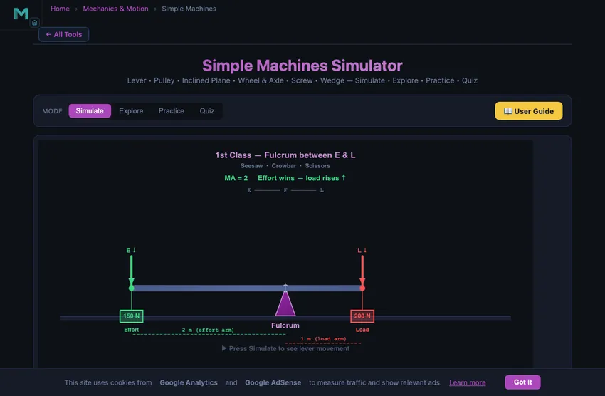
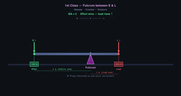
The simulator opens in Simulate mode with the Lever machine selected. The canvas shows an animated lever with effort and load arrows, and compact chips in its top-left corner read out MA, VR and efficiency live — plus a self-locking state for the screw, wedge and inclined plane. Fuller numbers, including the work in / work out / friction-loss breakdown, sit in the cards below.
Use the Machine pills to switch between the six machine types. Each machine has its own set of sliders and parameters. The four mode pills (Simulate, Explore, Practice, Quiz) at the top let you switch between hands-on simulation, concept study, random problem practice, and timed quizzes.
Presets — Wheelbarrow, Fishing Rod, Crane Pulley, Car Jack, Loading Ramp, Door Wedge and Well Windlass — configure realistic scenarios with a single click.
On the Lever and Inclined Plane the canvas is draggable: the cursor changes over it, and on the lever you grab the effort or the load clamp (whichever is nearer the pointer) and slide it along the beam, while on the ramp dragging up/down sets the angle. A drag is one undo step, and a plain click never changes anything.
3 Running the Demo
Select a machine type and adjust its parameters using the sliders. Press Simulate to watch the animated operation, and Reset to return to the starting position.
Lever: Choose 1st, 2nd, or 3rd class. Adjust effort, load, effort arm, and load arm. MA equals the effort arm divided by the load arm.
Pulley: Choose Fixed, Movable, Block & Tackle or Differential. Set the number of pulleys (1–6), effort, load, and diameter. MA for a block-and-tackle system equals the number of rope sections supporting the load. The Differential (Weston) chain block has two sheaves of diameters D and d cast together on one axle: one turn winds πD of chain on and pays πd off, so the load rises π(D−d)/2 and VR = 2D / (D−d) — 20 for 300 and 270 mm sheaves. With friction on its efficiency is an engineering estimate of 40 %, below 50 %, which is why the load stays where it is left without a brake.
Inclined Plane: Set the ramp angle, load weight, applied effort, and friction μ. Choose Lift Up or Lower Down. Effort to lift = W(sinθ + μcosθ); to hold or lower under control = W(sinθ − μcosθ). In Lower Down the effort slider is the restraint: below that figure the sledge descends, between it and the lifting effort friction holds it, and above the lifting effort it is pulled back up. When tanθ ≤ μ the load is self-locking and will not slide on its own.
Wheel & Axle: Adjust wheel radius and axle radius. MA equals wheel radius divided by axle radius.
Screw: Set pitch, handle length, mean thread diameter dm, and thread friction μ. Ideal MA = 2πL/p. Real efficiency η = tanλ / tan(λ + φ), where the lead angle λ = atan(p / πdm) and the friction angle φ = atan(μ). When φ ≥ λ the screw is self-locking.
Wedge: Adjust apex angle α, driving force, and face friction μ. Splitting load per face = F / (2·tan(α/2 + φ)). A wedge with half-angle ≤ friction angle is self-holding once driven.
Pulley realism: When friction is enabled, each sheave wastes ~4% of input energy to bearing drag and rope stiffness, so a 4:1 block-and-tackle delivers around 85% efficiency rather than 100%.
Use the top-bar “Include real-world friction” checkbox to toggle between ideal (frictionless) and real physics for all machines.
4 The 3D Workshop
Press 3D in the control strip under the canvas to see the same machine built at true scale in a workshop: a pivot trestle with a graduated beam and cast-iron test weights, a gantry with sheave blocks and laid rope (or a Weston chain block), a hinged ramp with a sledge and spring balance, a windlass on plummer-block stands, a bottle screw jack and a log split by a dead-weighted wedge. Every weight is drawn at the size its mass has in iron or steel (m = F/g), so 10 N and 500 N look as different as they are. The sliders, the Friction and SI/Imperial toggles, the presets and Simulate/Reset all work exactly as in 2D — the 3D view draws the same engine.
Tap the machine to run it, and tap again to set it back. Drag the part you would move with your hand: a lever’s rider along the beam (its arm changes), the ramp up or down (its angle changes), or the hauling rope, the sledge, the windlass rope, the jack’s tommy bar or the wedge to work the machine by hand. A machine that cannot move under the forces you set refuses, and says why. While it moves, the gold line measures what moved on the model — e.g. rope pulled 1.20 m · load rose 0.30 m · ratio 4.00 = VR.
Drag the background to look around, right-drag or Shift-drag to pan, pinch or Ctrl + scroll to zoom (a two-finger or wheel scroll always scrolls the page). The bar on the stage picks a view (Auto, Front, Side, Close-up; double-tap also gives the close-up) and turns the Forces arrows and part Labels on and off; on a desktop the view cube turns the camera to any face. Keys on the focused workshop: Enter run/reset, R reset, 1–6 machine, F forces, L labels, arrows orbit, +/− zoom, 0 reset the view. It works on a phone, but a larger screen is easier.
5 Behind the Physics
Explore mode offers twelve concept cards across three categories: Fundamentals (mechanical advantage, velocity ratio, efficiency, work & energy), Machine Types (lever classes, pulley systems, inclined plane, wheel & axle), and Advanced (screw, wedge, compound machines, energy conservation). Each card carries a definition, formula, a diagram drawn on the canvas, and a worked numeric example.
Use this mode to review key relationships: MA = Load/Effort, VR = distanceeffort/distanceload, and Efficiency = (MA/VR) × 100%. Understanding these three quantities is essential for any simple machines exam.
6 Try a Problem
Practice mode draws from eighteen randomised generators covering all six machines: lever MA and effort, pulley VR, block-and-tackle effort and the differential pulley’s VR, inclined-plane MA and effort both with and without friction, wheel-and-axle MA, screw MA and lead angle (with a self-locking check), wedge MA and splitting force, plus efficiency, velocity ratio from distances, work input and work output. A full step-by-step solution is shown after every answer, right or wrong.
Quiz mode presents 5 randomised questions per session, drawn from a mixed pool of multiple-choice and numeric-entry items. Questions cover machine identification, MA and VR calculations, lever classes, and efficiency. Your score and a per-question breakdown are shown at the end.
7 Things to Notice
- Compare ideal vs. real: Toggle “Include real-world friction” on and off to see how friction reduces MA and efficiency below the geometric VR.
- Compare lever classes: Switch between 1st, 2nd, and 3rd class levers to see how fulcrum position affects MA and the direction of effort.
- Add pulleys incrementally: Start with 1 pulley and add more. With friction on, watch efficiency drop ~4% per added sheave.
- Find the screw self-locking limit: Lower thread friction μ until φ drops below the lead angle λ — the chip on the canvas will switch from “SELF-LOCKING” to “REVERSIBLE”.
- Try lowering on the inclined plane: Switch direction to “Lower Down” and lower the angle until tanθ ≤ μ — the load becomes self-locking and won’t slide.
- Use presets (Wheelbarrow, Crane Pulley, Car Jack, Fishing Rod) for realistic scenarios.
- Watch the work cards: Work in, Work out and Lost to friction are shown for every machine, normalised to one unit of load movement. With friction off the first two are equal; switch friction on and the difference is exactly the loss, so Work out / Work in always reproduces the efficiency figure.
- The simulator works fully offline once loaded — ideal for classrooms without internet access.
Understanding Simple Machines — Mechanical Advantage, Velocity Ratio & Efficiency
A simple machine multiplies force by trading distance. Mechanical Advantage (MA) equals load divided by effort, Velocity Ratio (VR) equals effort distance divided by load distance, and Efficiency η equals MA divided by VR times 100 percent. Ideal machines have η = 100% so MA = VR; real machines lose energy to friction so η < 100%.
The Six Classical Simple Machines — Quick Reference
| Machine | Ideal MA | VR | Self-locking when |
|---|---|---|---|
| Lever | effort arm / load arm | = MA | n/a |
| Pulley (block & tackle) | n (rope segments) | = MA | n/a |
| Inclined plane | 1 / sin θ | = MA | tan θ ≤ μ |
| Wheel & axle | R / r | = MA | n/a |
| Screw | 2πL / p | = MA | φ ≥ λ (where tan λ = p / πdm, tan φ = μ) |
| Wedge | 1 / (2 tan(α/2)) | = MA | α/2 ≤ φ |
This simulator computes both the ideal and the real (friction-aware) values, plus self-locking detection for screws, wedges and inclined planes. Toggle the Friction chip on the canvas to compare ideal vs. real behaviour; toggle SI / Imperial to switch units across every slider, readout and calculation modal.
How Simple Machines Multiply Force
A lever multiplies force by using a rigid beam that pivots around a fulcrum. First-class levers (like a seesaw) have the fulcrum between the effort and the load; second-class levers (like a wheelbarrow) have the load between the fulcrum and effort; third-class levers (like a fishing rod) have the effort between the fulcrum and load. The mechanical advantage of a lever equals the effort arm divided by the load arm. A pulley system redirects or multiplies force using ropes threaded through wheels. Fixed pulleys change direction; movable pulleys provide mechanical advantage equal to the number of rope sections supporting the load. A block and tackle system combines both for even greater advantage.
Inclined Planes, Screws & Wedges
An inclined plane (ramp) reduces the effort needed to raise an object by spreading the work over a longer distance. Its ideal mechanical advantage is 1/sin(angle). The screw is essentially an inclined plane wrapped around a cylinder — one turn advances the screw by its pitch, while the effort travels a much larger circle (2 times pi times the handle length). The wedge is a double inclined plane that converts a horizontal force into two perpendicular splitting forces. The wheel and axle works like a rotating lever, where the mechanical advantage equals the wheel radius divided by the axle radius. All compound machines, from cars to cranes, are combinations of these six simple machines working together.
Archimedes’s Boast and What It Actually Means
“Give me a place to stand and I will move the Earth,” Archimedes is supposed to have said about levers. The boast is mathematically correct. A long enough lever multiplies force without limit. The catch is in the velocity-ratio penalty — you have to move the effort end a vast distance to shift the load end by a tiny one. Put numbers on it: the Earth weighs about 5.86×1025 N in its own gravity, so pushing with 1000 N needs MA ≈ 5.9×10²². Shifting the load end by a single millimetre then drags the effort end through 5.9×10¹⁹ m — about 6,200 light-years, or a few percent of the way across our galaxy. Force multiplication is real. The work you do is conserved.
A Pulley Worked Example — Lifting 200 kg with 50 N
You have a load of 200 kg (1962 N weight) and you want to lift it with about 50 N of pull on a rope. How many pulleys do you need?
- Required ideal MA: 1962/50 ≈ 40
- For a pulley system, MA equals the number of rope segments supporting the load. So you need 40 rope segments.
- That is impractical — even a heavy industrial 8-fall block (MA = 8) is enormous. Real pulleys for these loads run at 4−8 and the operator pulls harder, often through a powered winch.
- Real efficiency is well below ideal. A typical multi-fall block runs at about 70−85 % efficiency. To lift 200 kg with an 8-fall block at 75 % efficiency, the actual pull required is 1962/(8×0.75) = 327 N, not 245 N as the ideal MA = 8 predicts.
Pulley Systems — Fixed, Movable and Block and Tackle
“Pulley” is really three different machines, and most of the confusion in a physics class comes from treating them as one. This is what each arrangement does.
| System | Pulleys | Ropes supporting the load | MA | Effort to lift 600 N | What it is for |
|---|---|---|---|---|---|
| Fixed pulley | 1, anchored | 1 | 1 | 600 N | Changes direction only — pull down to lift up. No force gain. |
| Movable pulley | 1, on the load | 2 | 2 | 300 N | Halves the effort, but you pull upward and twice as far. |
| Gun tackle (1 fixed + 1 movable) | 2 | 2 | 2 | 300 N | Half the effort and a downward pull. The usual first real system. |
| Block and tackle (2 + 2) | 4 | 4 | 4 | 150 N | Workshop lifting tackle, engine hoists. |
| Block and tackle (3 + 3) | 6 | 6 | 6 | 100 N | Heavy rigging, where rope length is cheaper than muscle. |
One rule covers every row: the mechanical advantage equals the number of rope sections actually supporting the moving load — not the number of wheels, and not the total amount of rope. Count the strands running to the moving block. That is the velocity ratio too, so a system with MA = 4 needs four metres of rope pulled for every metre the load rises.
Using the simulator with this table: its pulley selector sets the number of supporting rope sections, which is the MA column above — not the number of wheels in the drawing. For a single movable pulley choose 2, for a gun tackle 2, for a 2 + 2 block and tackle 4. Only the fixed pulley uses 1.
The mistake to avoid. On a gun tackle, students routinely count three strands — the two holding the movable block and the one they are pulling on — and report MA = 3. The strand you pull runs away from the load over the fixed pulley, so it carries no part of the weight. Set 2 pulleys in the simulator, read the effort, and the arithmetic settles it: 600 N ÷ 2, not ÷ 3.
These are ideal figures. A real tackle loses 2–5% per sheave to bearing friction and rope stiffness, so a six-part system delivers nearer MA 5 than 6 — which is exactly what the efficiency section below is about.
Differential Pulley (Weston) — Velocity Ratio 2D / (D−d)
A differential pulley block, also called Weston’s differential pulley, reaches a velocity ratio of 20 or more with only two moving parts. Two sheaves of different diameters, D and d, are cast together on one axle in the upper block. An endless chain runs from the large sheave down round a movable pulley that carries the load, and back up to the small sheave. The rest of the chain hangs as a hand loop that the operator pulls.
Deriving the velocity ratio from one turn. When the upper sheaves make one full turn, the large sheave winds πD of chain onto the load side and the small sheave pays πd back off it. The loop holding the movable pulley shortens by π(D−d), so the load rises half of that, π(D−d)/2. The hand chain moves πD in the same turn. Dividing the two distances gives the velocity ratio of a differential pulley:
VR = πD ÷ π(D−d)/2 = 2D / (D−d)
The closer the two diameters, the larger the velocity ratio. The ratio depends only on the diameters, so the sheave size has no effect on it.
| Large sheave D | Small sheave d | VR = 2D/(D−d) | Ideal effort for 1000 N | Real effort at 40 % efficiency |
|---|---|---|---|---|
| 300 mm | 240 mm | 10 | 100 N | 250 N |
| 300 mm | 270 mm | 20 | 50 N | 125 N |
| 200 mm | 190 mm | 40 | 25 N | 62.5 N |
Why its efficiency is kept below 50 %. A machine whose efficiency is below 50 % cannot run backwards: when the operator lets go, friction holds the load where it is. That makes a plain differential block self-locking, so it needs no brake or pawl. Typical efficiencies are about 30–45 %, and the simulator uses 40 % as an engineering estimate.
Try it in the simulator: choose Pulley → Differential, or press the Chain Hoist (Weston) preset, which uses 300 mm and 270 mm sheaves. Press Simulate and read the two bench rules. The chain pulled divided by the load’s rise prints the velocity ratio of 20 as it runs. Turn friction on to see 150 N lift 1000 N where 125 N is needed.
Real Efficiency — Why Simple Machines Are Never 100%
The ideal-MA-equals-VR relation only holds for frictionless machines. In practice every type loses energy somewhere:
| Machine | Typical real efficiency | Where the losses go |
|---|---|---|
| Lever | 95−98 % | Pivot bearing friction; some bending in the beam |
| Inclined plane (greased steel slide, μ ≈ 0.2) | about 1/(1 + μ·cotθ); ~75 % at 30°. Dry steel-on-steel (μ ≈ 0.6) drops to ~50 % | Coulomb friction at the contact |
| Block & tackle | 70−85 % | Sheave bearing friction; rope bending stiffness at each wrap |
| Differential (Weston) pulley block | 30−45 % | Chain friction on both upper sheaves; kept below 50 % so the load cannot run back |
| Power screw (Acme, dry) | 20−40 % | Thread friction; can be self-locking, which is sometimes deliberate |
| Worm gear | 50−90 % | Sliding friction on the worm tooth flank |
| Hydraulic press | ~90 % | Pump losses; seal friction |
Power screws are the most striking case. A square-thread Acme screw might give 25 % efficiency — you put in 4 J of work to get 1 J of useful work out. The other 3 J turns into heat in the threads. The trade-off is self-locking: the screw will not back-drive under the load, which is what makes screw jacks and vice clamps useful at all.
Compound Machines — Where Real Engineering Lives
Almost nothing in real engineering uses one simple machine alone. The combinations are where the interesting design happens:
- A bicycle is a wheel-and-axle (pedals on crank, rear cog on hub) connected by a chain that is essentially a long flexible link. Top gear gives one mechanical advantage for cruising; bottom gear gives another for hills.
- A can opener is a wedge (the cutting blade) driven by a lever (the handle) using a wheel-and-axle (the gear that turns the can).
- A car jack (the screw-type kind in the boot) is a power screw driving an inclined plane geometry through a four-bar linkage. Force multiplication factor of 100 or more is routine.
- A crane is a class-3 lever (the boom) loaded at the end, raised by a block-and-tackle pulley system, powered by a winch driven by a gear train, controlled by hydraulics. Five simple-machine families in one device.
References
- Hibbeler — Engineering Mechanics: Statics, 14th ed., Chapter 8 (Friction) for power-screw and wedge calculations.
- Shigley — Mechanical Engineering Design, Chapter 8 (Power Screws) for the screw self-locking criterion.
- The Crosby Group — Rigging Handbook. Industry-standard reference for block-and-tackle efficiency and safe working loads.
Simple Machines in 3D — a Virtual Workshop at True Scale
The simulator also runs as a free 3D simulation in the browser, with no download. Press 3D in the control strip under the canvas, next to Reset (the page opens in 2D), and each of the six machines appears as real workshop apparatus built at true scale: a lever on a pivot trestle with a graduated beam and cast-iron test weights, a pulley gantry with sheave blocks and laid rope or a Weston chain block, a hinged inclined plane with a sledge and spring balance, a wheel and axle (windlass) on plummer-block stands, a bottle screw jack, and a log split by a dead-weighted wedge. Every weight is drawn at the size its mass would have in iron or steel (m = F/g), so a 10 N load and a 500 N load look as different as they are.
The 3D view draws the same calculation as the 2D picture, so mechanical advantage, velocity ratio and efficiency are identical in both. You can work each machine by hand: pull the hauling rope, push the sledge up the ramp, wind the windlass, turn the jack’s tommy bar or drive the wedge. A gold line measures what moved, for example rope pulled 1.20 m · load rose 0.30 m · ratio 4.00 = VR, so the velocity ratio is measured on the model rather than quoted from a formula. A machine that cannot move under the forces you set refuses, and says why.
Other simulators with the same kind of 3D view: the 3D engine simulator, the gearbox in 3D and the 3D free fall drop site.
Frequently Asked Questions
What are the six types of simple machines?
The six classical simple machines are the lever, pulley, inclined plane, wheel and axle, screw, and wedge. Every complex machine is a combination of these basic types. Each simple machine allows you to trade force for distance, making it easier to perform work.
What is the difference between mechanical advantage and velocity ratio?
Mechanical Advantage (MA) is the ratio of load to effort (MA = Load/Effort) and represents the actual force multiplication. Velocity Ratio (VR) is the ratio of the distance moved by the effort to the distance moved by the load (VR = deffort/dload) and represents the ideal force multiplication. Efficiency equals MA/VR times 100%.
What are the three classes of levers and how do they differ?
First-class levers (like a seesaw) have the fulcrum between the effort and load. Second-class levers (like a wheelbarrow) have the load between the fulcrum and effort, always providing mechanical advantage greater than 1. Third-class levers (like a fishing rod) have the effort between the fulcrum and load, always providing mechanical advantage less than 1 but gaining speed.
What is the velocity ratio of a differential pulley block?
The velocity ratio of a Weston differential pulley block is VR = 2D / (D−d), where D and d are the diameters of the large and small upper sheaves. In one turn the effort moves πD while the load rises π(D−d)/2. Sheaves of 300 mm and 270 mm give VR = 20. Its efficiency is usually below 50 %, which makes it self-locking, so the load stays where it is left without a brake.
Can I see simple machines in 3D?
Yes. Press 3D in the control strip under the canvas and the lever, pulley, inclined plane, wheel and axle, screw and wedge appear as real apparatus built at true scale in a virtual workshop. It runs free in the browser with no download, uses the same calculation as the 2D view, and lets you pull the rope, wind the windlass or turn the jack by hand to measure the velocity ratio yourself.
Explore Related Simulators
If you found this Simple Machines simulator helpful, explore our Newton’s Laws simulator, Friction simulator, Gear Trains simulator, Power Screw Calculator, and Torque & Rotation simulator.
Updated