Star-Delta (Y-Δ) Conversion
General Y-Δ Transform • 3-Phase Circuits • Balanced & Unbalanced Loads • Star-Delta Starter — Simulate • Starter • Calculate • Explore • Practice • Quiz

Display Controls
Live Equations every number on the canvas, derived
What if… what each control would do next
1 Overview — the six modes
The Star-Delta Simulator shows how a three-phase load behaves when its three impedances are joined in star (Y) or delta (Δ), and how to convert between the two. In star the line voltage is √3 times the phase voltage (VL = √3 × Vph) and the line current equals the phase current. In delta the phase voltage equals the line voltage and the line current is √3 times the phase current. Total power is P = √3 × VL × IL × cos(φ) in both.
- Simulate — a live three-phase load: star or delta, balanced or unbalanced, resistive or reactive, with phasors and waveforms.
- Starter — a real star-delta motor starter run-up: torque–speed curves, current and speed against time, contactor states and the open-transition spike.
- Calculate — the general three-terminal Y-Δ transform for any three impedances, complex or resistive.
- Explore — eight illustrated concepts with worked examples.
- Practice — fourteen problem generators with step-by-step solutions.
- Quiz — six questions drawn from a bank of twenty-two, options shuffled, every answer explained.
Built for electrical engineering students, trainees studying industrial three-phase systems, and electricians learning motor connections and Y-Δ starters.
2 Setting up the circuit

Simulate mode opens with a balanced star load, Z = 100 Ω, VL = 400 V, 50 Hz. The control panel sits above the canvas so the page reads in the order the work happens — set it up, watch it, then read the numbers below.
- Pick a Preset from the dropdown (400 V EU, 208 V US, 415 V delta motor, 690 V industrial, a PF-correction capacitor bank, or an unbalanced star) — or leave it on Custom and build your own.
- Toggle Star (Y) / Delta (Δ) and watch every readout, the drawing and the phasor diagram change together.
- Choose the load type: R, R–L or R–C. With a pure resistor the frequency pills genuinely do nothing, because X = 0 either way; add a reactance and 50 vs 60 Hz changes the impedance, the current and the power factor.
- Every slider has a companion number box — type an exact value and press Enter, or just tab away.
- Tick Unbalanced load to give the three phases different impedances (the drawing scales each impedance block, so the picture really is unbalanced), then tick Neutral isolated to see the star point float.
3 Reading the canvas
The Display Controls chip at the top-left of the canvas holds six switches — conversion equations, phasor diagram, waveforms, labels & values, animate current, and the background grid — plus a Reset display button. Your choices are remembered between visits.
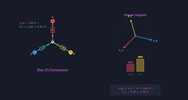
- Phasor diagram. In star it draws the three line-to-neutral voltages with the dashed VA − VB chord that produces the √3. In delta it draws the three line voltages with the branch-current difference that produces the same √3 on the current side. Branch currents are the dashed green phasors; their angle behind the voltage is φ.
- Waveforms. Three voltage waves plus the phase-A line current on its own scale, so the lag or lead is visible even when the current is thousands of times smaller than the voltage.
- Right-click the canvas for Show calculation, Copy values, Export CSV, Export PNG, Toggle grid and Reset.
- The Show Calculation button at the bottom-right opens a step-by-step derivation of everything on screen, rebuilt from the current state each time you open it.
Readout cards below the canvas give line and phase voltage, line and phase current, neutral current (or star-point shift), P, Q, S, power factor, |Z| and the equivalent ZY / ZΔ pair. Cards that do not apply to the current state are hidden rather than showing a dash.
4 Starter mode — the motor run-up
Starter mode runs a cage induction motor up to speed through a star-delta starter, using the approximate per-phase equivalent circuit. Choose a motor preset (7.5–75 kW), or set the rating, voltage, pole count and frequency yourself.
- Pick a driven load — unloaded, fan (T ∝ n²), pump, or constant torque — and how much of rated torque it demands at full speed.
- Inertia H stretches or shortens the run-up without ever changing the ⅓ ratios, which come from the winding voltage alone.
- Change over by speed or by timer, the way a real starter relay does, and watch the current spike when the delta contactor recloses while the motor is still slipping. Change over later and the spike shrinks.
- Press Run to play the start, Rewind to return to standstill. The left graph shows the torque–speed characteristics in star and delta against the load curve; the right graph shows line current and speed against time, with the star, open-transition and delta periods shaded.
- Switch to Direct-on-line to compare. Set a constant-torque load above about 35% and the motor will visibly stall in the star position — which is exactly why star-delta is a fan-and-pump method.
5 Calculate mode — the general Y-Δ transform
Calculate mode does the network theorem, not the balanced shortcut. Enter three impedances as R and X, choose the direction, and it returns the three equivalent arms in both rectangular and polar form, with the substituted formulas in the Live Equations panel.
- Delta → Star: ZA = ZAB × ZCA / (ZAB + ZBC + ZCA) — multiply the two arms that touch the node.
- Star → Delta: ZAB = (ZAZB + ZBZC + ZCZA) / ZC — divide by the arm opposite the side.
- Put the same value in all three boxes and the tool confirms the balanced case: ZΔ = 3 ZY exactly. Make them unequal and it warns you that the 3× rule no longer applies.
- Type a reactance into the X boxes and the transform still holds — which is what makes it useful for AC bridge networks, not just resistor puzzles.
6 Keyboard, export and field tips
- Keyboard: Ctrl+Z undo, Ctrl+Shift+Z redo, Esc closes the calculation modal or the right-click menu. In Practice, Enter checks your answer and then moves on.
- Export CSV writes a line-voltage sweep in Simulate, the full run-up trace in Starter, and the input and output arms in Calculate. Export PNG saves the canvas with a watermark.
- Remember the √3 (≈ 1.732): in star VL = √3 Vph; in delta IL = √3 Iph. It is the length of the difference of two unit phasors 120° apart, not a fudge factor.
- The same three impedances draw three times the power in delta as in star, because each sees √3 times the voltage and P ∝ V².
- P = √3 VLILcosφ is only valid for a balanced load. Tick Unbalanced and the tool sums the three branches instead, and says so.
- In a 400 V system, star gives 231 V line-to-neutral — which is where domestic 230 V comes from.
- A broken neutral on an unbalanced star load is genuinely dangerous: switch Neutral isolated on with an unbalanced load and watch one phase voltage climb well above 230 V.
Understanding Star-Delta (Y-Δ) Conversion — Free Interactive 3-Phase Circuit Simulator
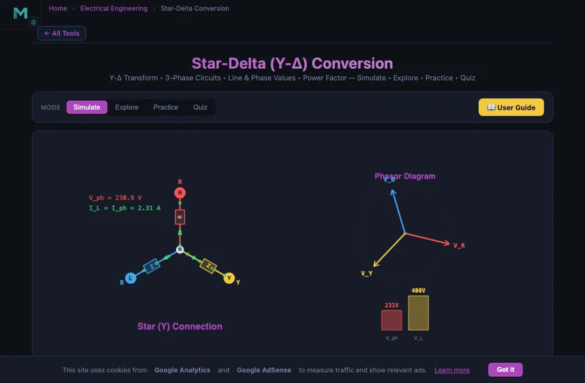
Star-delta conversion (also known as Y-Δ transformation) is a fundamental technique in electrical engineering for analyzing 3-phase circuits. In a star (Y) connection, three impedances share a common neutral point, while in a delta (Δ) connection, they form a closed triangle between the three line terminals. This simulator lets you toggle between both configurations and observe how line voltages, phase voltages, line currents, and phase currents change in real time. Understanding these relationships is essential for power distribution, motor starting, and industrial electrical systems.
Star (Y) Connection — Voltage and Current Relationships
In a star connection, each impedance is connected between a line terminal and the neutral point. The key relationships are: Vline = √3 × Vphase and Iline = Iphase. This means the line voltage is 1.732 times larger than the phase voltage, while the line current equals the phase current. Star connections are commonly used in power distribution because they provide access to two voltage levels (e.g., 230V phase and 400V line in European systems) and allow a neutral wire for single-phase loads.
Delta (Δ) Connection — Voltage and Current Relationships
In a delta connection, each impedance is connected between two line terminals, forming a triangle. The key relationships are: Vline = Vphase and Iline = √3 × Iphase. Here the phase voltage equals the full line voltage, but the line current is 1.732 times the phase current. Delta connections are widely used for motor windings and high-power loads because they can handle higher power without a neutral conductor.
Star and Delta Connection Formulas — Quick Reference
Every relationship a three-phase problem needs, in one table. All voltages and currents are RMS; φ is the angle between the phase voltage and the phase current.
| Quantity | Star (Y) | Delta (Δ) |
|---|---|---|
| Phase voltage Vph | VL / √3 | VL |
| Line voltage VL | √3 × Vph | Vph |
| Phase current Iph | Vph / Z | Vph / Z |
| Line current IL | Iph | √3 × Iph |
| Angle between VL and Vph | 30° | 0° |
| Angle between IL and Iph | 0° | 30° |
| Real power P | √3 × VL × IL × cosφ = 3 × Vph × Iph × cosφ | |
| Reactive power Q | √3 × VL × IL × sinφ | |
| Apparent power S | √3 × VL × IL = √(P² + Q²) | |
| Power with the same Z | P | 3P |
| Neutral current (balanced) | 0 | no neutral |
| Equivalent impedance | ZΔ = 3 × ZY | |
Worked at 400 V, 50 Hz with Z = 100 Ω per phase: in star Vph = 400/1.732 = 231 V, Iph = IL = 2.31 A and P = 1600 W. Reconnect the same three impedances in delta and Vph = 400 V, Iph = 4 A, IL = 6.93 A and P = 4800 W — exactly three times.
How Do You Convert Delta to Star? The General Y-Δ Transform
The ZΔ = 3 ZY rule everyone memorises is only the balanced special case. The real theorem works for any three impedances, and it is what you need when a bridge network refuses to reduce by series and parallel combination.
Delta → star. Each star arm is the product of the two delta arms that touch that node, divided by the sum of all three:
| Delta → Star | Star → Delta |
|---|---|
| ZA = ZAB ZCA / ΣZ | ZAB = (ZAZB + ZBZC + ZCZA) / ZC |
| ZB = ZAB ZBC / ΣZ | ZBC = (ZAZB + ZBZC + ZCZA) / ZA |
| ZC = ZBC ZCA / ΣZ | ZCA = (ZAZB + ZBZC + ZCZA) / ZB |
| ΣZ = ZAB + ZBC + ZCA • valid for complex impedances, not just resistors | |
Example: a delta of 10 Ω, 20 Ω and 30 Ω. ΣZ = 60 Ω, so ZA = (10 × 30)/60 = 5 Ω, ZB = (10 × 20)/60 = 3.33 Ω and ZC = (20 × 30)/60 = 10 Ω. Notice that no single number is one third of anything — the 3× rule genuinely does not apply once the arms differ. Put all three equal to Z and the formula collapses: ZA = Z²/3Z = Z/3, which is where ZΔ = 3 ZY comes from. The Calculate mode of the simulator does both directions for arbitrary complex impedances and shows the substituted arithmetic.
Y-Δ Conversion in Three-Phase Loads
For a balanced three-phase load the transform reduces to ZΔ = 3 × ZY, and the total power is identical either way for equivalent loads: P = √3 × VL × IL × cos(φ). What changes when you reconnect the same three impedances is the voltage each one sees — √3 times more in delta — and since power goes as the square of voltage, the load draws three times the power. Read that backwards and you have the star-delta motor starter.
The Star-Delta Motor Starter — The Practical Application
Three-phase induction motors above about 7.5 kW have a starting problem. At standstill (full slip), the motor presents very low impedance to the supply, drawing 5−7 times its full-load current for a few seconds. On large installations this causes voltage dips on the supply, trips upstream protection, and stresses the motor windings.
The star-delta starter solves this elegantly. Connect the motor windings in star for the initial 5−10 seconds of starting. Each winding sees Vline/√3 instead of full Vline, so starting current drops to about one-third of the direct-on-line value. The motor accelerates to about 70−75% of full speed. Then switch to delta — each winding sees full Vline and the motor runs normally. The trade-off is reduced starting torque (also one-third of DOL), so star-delta only works for motors started on light loads or no load.
Why Modern Motors Use Soft Starters Instead
Star-delta starters dominated from the 1920s through the 1990s. Three issues drove their replacement:
- Voltage surge at transition. The brief open-circuit moment between star contactor opening and delta contactor closing produces a high-voltage transient as the motor’s back-EMF momentarily faces no supply. Modern designs (Closed Transition or Wauchope) mitigate this with resistors, but it adds complexity.
- Limited torque control. The motor accelerates uncontrollably during the star period.
- Mechanical wear. The high-current contactor for switching star-delta is a wear item that needs periodic replacement.
Modern electronic soft starters use SCRs to ramp the motor voltage smoothly from a low value to full Vline over a programmable 5−30 seconds. Variable Frequency Drives (VFDs) go further by ramping frequency too. Both give precise torque control and zero electrical transients. Star-delta starters still exist on legacy installations and for very large motors (above 200 kW) where electronic alternatives are expensive, but they are no longer the default choice.
What Happens When the Load Is Unbalanced?
A balanced load has three equal impedances, so its three currents — equal in size and 120° apart — sum to zero and the neutral carries nothing. Unbalance breaks that cancellation, and what happens next depends entirely on the neutral.
With the neutral connected (a 4-wire system) each phase still sees VL/√3, and the difference simply returns through the neutral conductor. That is the whole point of the fourth wire, and it is why the neutral in a domestic distribution board is sized for real current rather than treated as a spare.
With the neutral disconnected (3-wire, or a broken neutral) no current can return, so the star point itself moves until the three currents do sum to zero. Its position is the Millman voltage, VN = ΣEiYi / ΣYi. The lightly loaded phase then rises well above 230 V and the heavily loaded one collapses. Tick Unbalanced load and Neutral isolated in the simulator and watch the three phase voltages spread apart — that spread is what destroys appliances when a neutral fails.
Does the Supply Frequency Matter?
Only if the load is reactive. A pure resistance behaves identically on 50 Hz and 60 Hz. Add inductance and XL = 2πfL rises with frequency, so the impedance rises, the current falls and the power factor gets worse — the same motor winding really does present a different load on 60 Hz than on 50 Hz. Add capacitance and XC = 1/(2πfC) falls with frequency, so the current rises. Switch the load type in the simulator from R to R–L and the frequency pills stop being decorative.
References
- Chapman, S. J. — Electric Machinery Fundamentals, 5th ed., Chapter 7 (Induction Motors).
- IEC 60947-4-1 — Low-voltage switchgear and controlgear — Contactors and motor-starters.
- NEMA MG 1 — Motors and Generators, the North American standard for motor ratings and starting requirements.
Explore Related Simulators
If you found this Star-Delta Conversion calculator helpful, explore our Ohm’s Law & DC Circuits simulator, RLC Circuit simulator, Induction Motor simulator, the PLC Ladder Logic simulator — a star-delta starter is the classic first ladder program — Transformer simulator, and Wheatstone Bridge simulator for more hands-on electrical engineering practice.
Updated