Cam & Follower Mechanism
Profile Design & Motion Diagrams • Displacement • Velocity • Acceleration — Simulate • Explore • Practice • Quiz
1 Overview
The Cam & Follower Simulator lets you design and analyse cam mechanisms with different motion laws, follower types, and cam profiles. A cam is a rotating or sliding element that imparts a desired motion to a follower through direct contact. This simulator visualises the animated cam rotation alongside real-time displacement diagrams, velocity curves, and acceleration plots.
You can explore five motion laws — eccentric, SHM, uniform velocity, uniform acceleration, and cycloidal — and three follower types: flat-face, roller follower, and knife-edge. The tool helps you understand critical design parameters including base circle radius, lift (stroke), pressure angle, and the dwell-rise-return sequence that defines cam timing.
2 Loading the Mechanism

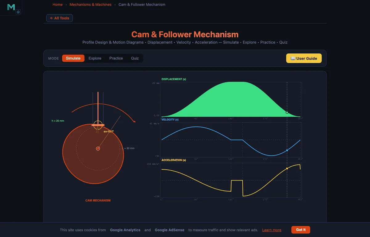
The simulator opens in Simulate mode with an eccentric cam preset. The canvas shows the animated cam rotating with the follower moving up and down, alongside real-time motion diagrams.
- Select a Cam Type (Eccentric, SHM, Uniform Velocity, Uniform Acceleration, or Cycloidal) to change the motion law.
- Adjust Base Circle Radius and Lift sliders to change cam geometry.
- Choose a Follower Type (Flat, Roller, or Knife-edge) to see how contact geometry affects the cam profile.
- Set the RPM to control animation speed.
- Load industry presets like Engine Valve, Printing Press, Textile Loom, or Packaging Machine.
Readout cards display current cam angle, displacement, velocity, acceleration, and peak values in real time.
3 Watching the Motion
The left side of the canvas shows the animated cam mechanism with the follower tracing the cam profile. The right side displays synchronised motion diagrams: displacement, velocity, and acceleration plotted against cam angle. A moving crosshair tracks the current operating point on all curves simultaneously.
Each motion law produces distinct diagram shapes. SHM gives smooth sinusoidal displacement but has acceleration discontinuities (jerk) at stroke boundaries. Cycloidal motion eliminates jerk entirely, making it ideal for high-speed applications. Uniform velocity produces linear displacement but theoretically infinite acceleration at transitions. Uniform acceleration (parabolic) gives constant acceleration in each half-stroke.
Use Play/Pause to freeze the animation at any angle, and Reset Angle to return to 0°.
4 Geometry & Theory
Switch to Explore to study 12 concepts across three categories:
- Cam Basics — Cam types (disc, cylindrical, eccentric), follower types (flat, roller, knife-edge), follower motion (translating vs oscillating), and terminology (base circle, trace point, pitch curve).
- Motion Laws — SHM, cycloidal, uniform velocity, uniform acceleration, and polynomial motion programs with displacement, velocity, and acceleration equations.
- Design — Pressure angle limits, undercutting avoidance, base circle sizing, cam profile construction methods, and dwell-rise-return timing design.
5 Try a Problem
Practice generates random problems on cam motion calculations — maximum velocity, maximum acceleration, follower displacement at a given angle, and cam sizing. Each problem provides a step-by-step solution on incorrect answers.
Quiz presents 5 randomised questions from a pool of 15, covering motion law comparisons, pressure angle concepts, and numerical cam design problems.
6 Design Notes
- Compare SHM and Cycloidal side by side — cycloidal has zero acceleration at stroke boundaries, making it superior for high-speed applications.
- Increasing the base circle radius reduces the pressure angle and risk of undercutting — always check these limits in real designs.
- The roller follower converts sliding friction to rolling friction, improving efficiency at higher speeds.
- Remember: v_max for cycloidal motion = 2hω/β, while a_max = 2πhω²/β².
- Use the Presets to see realistic parameter combinations for engine valves, printing presses, and packaging machinery.
- Pay attention to the acceleration diagram shape — discontinuities cause vibration and noise in real cam systems.
Cam and Follower Mechanisms — Profile Design and Motion Analysis
Cam and follower mechanisms are fundamental components in mechanical engineering used to convert rotational motion into reciprocating (linear) motion. A cam is a rotating or sliding piece of machinery that transmits a desired motion to a follower through direct contact. The follower is the output element that traces the cam profile and moves accordingly — typically in a straight line (translating follower) or along an arc (oscillating follower). These mechanisms are found in internal combustion engines, textile machinery, printing presses, packaging equipment, and automated manufacturing systems.
Types of Cams and Followers
Cams are classified by their shape and motion. A disc cam (or plate cam) is the most common type, where the cam profile is machined on the face of a rotating disc. A cylindrical cam has a groove cut into a cylinder surface. An eccentric cam is the simplest form — a circular disc mounted off-centre on a shaft, producing simple harmonic follower motion. Followers are classified by the shape of their contact surface: a flat-face follower has a wide, flat contact surface and distributes the contact force over a larger area, reducing wear. A roller follower uses a small roller at the contact point to convert sliding friction into rolling friction, improving efficiency. A knife-edge follower has a sharp point of contact, allowing it to follow complex cam profiles precisely but wearing faster due to high contact stress.
Motion Laws for Cam Design
The cam profile is designed based on the desired motion law of the follower. Simple Harmonic Motion (SHM) produces a sinusoidal displacement curve with smooth acceleration but has a discontinuity in acceleration at the start and end of the stroke, causing jerk. The displacement equation is s = (h/2)(1 − cos(πθ/β)), where h is the lift, θ is the cam angle, and β is the rise angle. Uniform velocity gives a linear displacement (s = hθ/β) but produces theoretically infinite acceleration at the transitions, making it unsuitable for high-speed applications without modification. Uniform acceleration and deceleration (parabolic motion) provides constant acceleration in the first half of the stroke and constant deceleration in the second half, with vmax = 2hω/β and amax = 4hω²/β². Cycloidal motion is considered the ideal motion law because it has zero acceleration at both ends of the stroke, eliminating jerk. Its displacement equation is s = h(θ/β − sin(2πθ/β)/(2π)), with vmax = 2hω/β and amax = 2πhω²/β².
Key Design Parameters
The base circle is the smallest circle that can be drawn from the cam centre, tangent to the cam profile. The trace point is the point on the follower (centre of the roller for roller followers, or the contact point for knife-edge followers) whose path defines the pitch curve. The pressure angle is the angle between the direction of the follower motion and the normal to the pitch curve — it should be kept below 30° for translating followers to prevent jamming. Undercutting occurs when the pitch curve has a radius of curvature less than the roller radius, making the cam profile self-intersecting and impossible to manufacture. Increasing the base circle radius reduces both the pressure angle and the risk of undercutting.
Five Motion Profiles, Compared on the Same Cam
Five common follower motion laws produce wildly different cam behaviour. Here is what each one feels like when you actually run it on a bench, alongside the displacement-velocity-acceleration trinity:
| Motion law | How it sounds | vmax coefficient | amax coefficient | Where it lives in practice |
|---|---|---|---|---|
| Eccentric (simple harmonic, single-lobe) | Smooth, quiet at low RPM, harsh at high RPM | π/2 (1.57) | π²/2 (4.93) | Marine pumps, slow-speed dosing machines |
| Uniform velocity | Loud bang at each end of stroke | 1.00 | infinite (at transitions!) | Hand-cranked equipment only; never high speed |
| Uniform acceleration (parabolic) | Audible click at midpoint; quieter than SHM | 2.00 | 4.00 | Older valve trains, packaging conveyors |
| Simple harmonic motion (full) | Smooth at low to medium RPM, jerk noise at high RPM | π/2 (1.57) | π²/2 (4.93) | Spring-loaded poppet valves, sewing machine needle bars |
| Cycloidal | Smoothest of the five; quietest at high RPM | 2.00 | 2π (6.28) | Modern automotive cams, high-speed textile machines |
The numbers in the vmax and amax columns multiply the basic scaling: vmax = coefficient·(hω/β), amax = coefficient·(hω²/β²). What this hides is the more important comparison: the jerk, which is da/dt. Cycloidal has finite jerk throughout. Parabolic has a step discontinuity in jerk at the midpoint. SHM and eccentric have infinite jerk at start and end of lift. Uniform velocity is the worst case — infinite acceleration plus infinite jerk at every transition.
Why Jerk Matters — The Difference Between a Quiet Engine and a Rattling One
Jerk — the rate of change of acceleration — is the quantity that determines how a cam-follower system sounds and how long it lasts. The follower mass times the jerk equals the rate of change of the contact force. When jerk is high, the contact force changes abruptly, which has three consequences:
- The follower can leave the cam. At high RPM, if the spring force preloading the follower is less than the inertial force, the follower physically lifts off the cam surface. When it lands again, you hear the click. In a high-revving racing engine the noise is the valve train protesting the chosen profile.
- Contact stress spikes locally. A sudden jerk produces a momentary impulsive force, much higher than the steady-state contact force. The Hertz contact stress equation is non-linear in force, so a 2× force spike gives more than 2× contact stress. Surface pitting at the points of jerk discontinuity is the long-term failure mode.
- Excited vibration modes. The follower train (rocker, push-rod, valve) has its own natural frequencies. High jerk inputs harmonics into the train at frequencies that can resonate with these modes, producing audible whine and accelerated wear.
That is why the move from parabolic to cycloidal cams in the 1960s and 1970s was such a step change in engine quietness and reliability — not because the average forces were lower, but because the jerk content was bounded.
A Practical Case — Valve Timing in a Small Engine
Take an example from a 125 cc single-cylinder petrol engine. The intake cam profile is designed for:
- Valve lift h = 7 mm
- Total opening duration (cam angle) β = 110° for full lift and return = 1.92 rad
- Engine speed at peak power: 8000 rpm. Camshaft (1:2 ratio) runs at 4000 rpm = 419 rad/s
- Cycloidal motion law selected for quietness
The peak valve speed and acceleration come out as:
| Quantity | Formula | Working | Result |
|---|---|---|---|
| Maximum lift velocity | vmax = 2·h·ω/β | 2 × 0.007 × 419 / 1.92 | 3.05 m/s |
| Maximum lift acceleration | amax = 2π·h·ω²/β² | 2π × 0.007 × 419² / 1.92² | 2,000 m/s² (~204 g) |
| Required spring force (mvalve = 30 g) | F = m·a + valve closing force | 0.030 × 2000 + 30 | 90 N |
Two hundred g of acceleration on a 30 gram valve sounds extreme, but it is routine for modern engines. The valve spring has to keep the follower pressed against the cam under this acceleration; if the spring is too soft, the valve floats. Race engines push this further; F1 engines historically used pneumatic valve springs because no coil spring could close fast enough at 18,000 rpm.
Pressure Angle — The Hidden Constraint That Limits Lift
The pressure angle is the angle between the direction the follower wants to move and the direction the cam profile pushes it. A large pressure angle means much of the cam force goes sideways into the guide bushings, where it produces side load and friction rather than useful work. The rule of thumb is to keep the pressure angle below 30° for translating roller followers, below 45° for oscillating followers.
The pressure angle depends on the cam profile, the base circle radius, and the eccentricity of the follower path:
tanφ = (v − eω) / (ω(Rp + s))
where Rp is base circle radius, e is the follower offset from the cam axis, s is the current lift, and v is the follower velocity. Three knobs to tune: bigger base circle reduces the angle, smaller lift reduces it, slower lift (longer β) reduces it. The simulator’s pressure-angle readout flashes red when it crosses 30° so you can see immediately when a design needs to be relaxed.
Books and References for Cam Design
- Norton, R. L. — Cam Design and Manufacturing Handbook, 2nd ed., Industrial Press. The single most useful reference. Includes the full library of motion functions and pressure-angle nomograms.
- Norton, R. L. — Design of Machinery, 6th ed., Chapter 8 (Cam Design). The textbook version, more accessible for first-time students.
- Shigley & Uicker — Theory of Machines and Mechanisms, 5th ed., Chapter 6 (Cams).
- Heywood, J. B. — Internal Combustion Engine Fundamentals, 2nd ed. The chapter on valve dynamics covers automotive cam-follower interaction.
- ISO 53:1998 — Cylindrical gears for general and heavy engineering — Basic rack tooth profile. Useful for the generation principles that apply to cam-cutter geometry.
How to Use This Simulator
In Simulate mode, select a cam type (Eccentric, SHM, Uniform Velocity, Uniform Acceleration, or Cycloidal), set the base circle radius and lift using sliders, choose a follower type, and adjust the RPM. The left side shows the animated cam rotating with the follower moving up and down. The right side displays real-time displacement, velocity, and acceleration diagrams with a moving crosshair showing the current angle. Use presets to load common industrial configurations. Switch to Explore mode to study 12 concepts across Cam Basics, Motion Laws, and Design categories. Practice mode generates calculation problems, and Quiz mode tests your understanding with 5 randomised questions from a pool of 15.
Explore Related Simulators
If you found this Cam & Follower simulator helpful, explore our Four-Bar Linkage simulator, Slider-Crank simulator, and Gear Trains simulator for more hands-on practice.