Four-Bar Linkage Simulator
Mechanism Design & Analysis • Grashof Condition • Transmission Angle • Coupler Curves — Simulate • Explore • Practice • Quiz
1 Overview
The Four-Bar Linkage Simulator is an interactive educational tool that lets you design, animate, and analyse four-bar linkage mechanisms in real time. A four-bar linkage is the simplest closed-loop kinematic chain, consisting of four rigid links connected by revolute (pin) joints. It is the foundation of countless engineering mechanisms including windshield wipers, rocking chairs, sewing machines, and aircraft landing gear.
This simulator covers the complete range of four-bar mechanism types: crank-rocker, double-crank (drag link), double-rocker, and parallelogram configurations. You can verify the Grashof condition, visualise beautiful coupler curves, monitor the transmission angle in real time, and track angular velocities through the full rotation cycle. The tool provides four learning modes to build deep understanding of mechanism kinematics and the degrees of freedom concept.
2 Loading the Mechanism

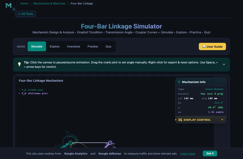
When you first load the simulator, you are in Simulate mode with a default crank-rocker preset. The animated four-bar mechanism rotates continuously on the canvas, and readout cards display real-time values below. To begin exploring:
- Use the link-length sliders (Ground, Crank, Coupler, Follower) to change the geometry of the mechanism and observe how its behaviour changes. For precise geometry, type an exact value — including decimals such as 45.5 or 100.25 — into the text box beside each slider, or nudge it with the −/+ buttons. The view automatically zooms to fit the mechanism, whatever the link proportions.
- Select a preset (Crank-Rocker, Double-Crank, Triple-Rocker, or Parallelogram) to load a classic configuration instantly.
- Toggle Show Coupler Curve to trace the path of the coupler midpoint as the crank completes a full revolution.
- Enable Show Velocity to visualise angular velocity vectors on the links.
- Adjust the RPM slider to speed up or slow down the animation for detailed observation.
The readout cards update in real time showing mechanism type, Grashof condition, crank angle, transmission angle, coupler angle, and angular velocity of the follower.
3 Watching the Motion
Simulate mode is the primary interactive workspace. The canvas renders an animated four-bar linkage with colour-coded links: the ground link (fixed frame), input crank, coupler, and output follower. As the crank rotates, the simulator solves the loop-closure equation analytically to compute coupler and follower angles at every frame.
The Grashof condition is evaluated automatically: if s + l ≤ p + q (where s is the shortest link, l the longest, and p, q the remaining two), at least one link can make a full rotation. The mechanism type is classified and displayed in real time. When link lengths create an impossible configuration, a warning message appears.
The transmission angle (μ) measures force transmission quality between the coupler and follower. Values near 90° are ideal; below 40° the mechanism enters a poor-transmission zone highlighted in the readout. The coupler curve feature traces the path of the coupler midpoint over one complete revolution, producing fascinating shapes used in path-generation design problems.
4 Geometry & Theory
Switch to Explore mode to study 12 key concepts organised into three categories:
- Linkage Basics — Four-bar structure, Grashof criterion, mechanism classification (crank-rocker, double-crank, double-rocker), link terminology, and degrees of freedom.
- Kinematics — Position analysis using the loop-closure equation, velocity analysis, angular velocity relationships, transmission angle significance, and coupler curve generation.
- Design — Path generation, function generation, motion generation (rigid-body guidance), and practical applications in real-world machines.
Each concept card includes clear explanations, formulas, diagrams, and worked examples to build thorough understanding of four-bar linkage theory.
5 Try a Problem
Practice mode generates unlimited random problems covering Grashof analysis, transmission angle calculation, link classification, and mechanism design. Enter your numerical answer and receive instant feedback with tolerance-based grading. If incorrect, a step-by-step solution is provided. A running score tracks your progress.
Quiz mode presents 5 randomised multiple-choice questions drawn from a pool of 15, covering both conceptual understanding and numerical problem-solving. After completing the quiz, you receive a score with detailed review of each question showing the correct answer alongside your response.
6 Design Notes
- Start with the presets to see how different link proportions produce fundamentally different mechanism types before adjusting sliders manually.
- Watch the transmission angle readout as the crank rotates — this is the single most important quality metric for a four-bar mechanism in practical design.
- Enable the coupler curve and experiment with different link lengths to see the enormous variety of curves a simple four-bar mechanism can produce.
- In Practice mode, remember that the Grashof condition compares s + l with p + q — identify the shortest and longest links first before classifying.
- The parallelogram linkage is a special case where opposite links are equal — it maintains parallel orientation and is used in pantographs and drafting machines.
- Use Explore mode as a reference before attempting Practice problems to review formulas and worked examples.
Four-Bar Linkage Mechanism — Design, Analysis & Simulation
The four-bar linkage is the simplest and most widely used closed-loop mechanism in mechanical engineering. It consists of four rigid links connected by four revolute (pin) joints, forming a closed kinematic chain. One link is fixed (the ground or frame), the input link (crank) is driven at a known angular velocity, the output link (follower or rocker) moves in response, and the connecting link (coupler) transmits motion between the crank and follower. This mechanism is the building block of countless real-world machines, from windshield wipers and sewing machines to aircraft landing gear and automotive suspensions.
Understanding the four-bar linkage is essential for any student of kinematics of machines or theory of machines. The mechanism can produce a wide variety of output motions depending on the relative lengths of its links. By changing link proportions, engineers can design mechanisms that convert continuous rotation into oscillation (crank-rocker), produce continuous rotation at the output (double-crank or drag link), or create oscillation at both the input and output (double-rocker). The parallelogram linkage, a special case, maintains parallel orientation between opposite links and is used in drafting machines, pantographs, and locomotive wheel couplings.
| Mechanism Type | Shortest Link | Input Motion | Output Motion | Grashof? |
|---|---|---|---|---|
| Crank-Rocker | Crank (input) | Full rotation | Oscillation | Yes |
| Double-Crank | Ground (frame) | Full rotation | Full rotation | Yes |
| Double-Rocker | N/A (non-Grashof) | Oscillation | Oscillation | No |
| Parallelogram | Both pairs equal | Full rotation | Full rotation | Yes (special) |
What is Grashof's criterion and how does it classify four-bar linkages?
The behaviour of a four-bar linkage is governed by Grashof's law, which states that for at least one link to make a full revolution, the sum of the shortest and longest link lengths must be less than or equal to the sum of the remaining two link lengths: s + l ≤ p + q. If this condition is satisfied, the linkage is classified as a Grashof mechanism. When the shortest link is the crank (input), the mechanism is a crank-rocker. When the shortest link is the ground (frame), both the crank and follower can rotate fully, producing a double-crank (drag link). When the shortest link is the coupler, the result is a Grashof double-rocker — the coupler can make full revolutions relative to the other links, but neither side link rotates fully relative to ground. If the Grashof condition is not satisfied, no link can complete a full revolution, and the mechanism is classified as a non-Grashof double-rocker (also called a triple-rocker in some texts).
What is the transmission angle and why does it matter in mechanism design?
The transmission angle (μ) is the acute angle between the coupler and the follower link. It is a critical measure of force transmission quality in a four-bar mechanism. When the transmission angle approaches 90°, force is transmitted most efficiently. As the transmission angle drops below 40°, mechanical advantage deteriorates significantly, and the mechanism may experience difficulty in transmitting motion. Designers typically aim to keep the minimum transmission angle above 40° throughout the full cycle of operation. This simulator highlights the transmission angle in real time and warns when it falls into the poor-transmission zone.
How are coupler curves generated and used in path generation?
When a point on the coupler link is traced as the crank rotates through a full revolution, the resulting path is called a coupler curve. Four-bar coupler curves can produce an astonishing variety of shapes — circles, ellipses, figure-eights, and complex higher-order curves. Engineers use coupler curves for path generation, designing mechanisms where a specific point must follow a desired trajectory. The Atlas of Coupler Curves, cataloguing thousands of these shapes, remains an important reference in mechanism design. In this simulator, enabling the coupler curve toggle traces the midpoint of the coupler in real time, building up the complete curve over one revolution.
How does the loop-closure equation solve for four-bar linkage positions?
The kinematic analysis of a four-bar linkage begins with the loop-closure equation, which expresses the constraint that the four links form a closed polygon. Given the crank angle θ2, the coupler angle θ3 and follower angle θ4 can be found analytically using Freudenstein's equation or direct geometric methods. These analytical solutions avoid iterative procedures and are ideal for real-time simulation. Velocity analysis follows by differentiating the position equations, yielding the angular velocities of the coupler and follower as functions of the crank speed.
Grashof in 30 Seconds — The Trick I Teach Every Class
Grashof’s condition (s + l ≤ p + q) sounds abstract. Here is the version that sticks in students’ heads: identify the shortest link, identify the longest link, add their lengths, and compare to the sum of the other two. If shortest plus longest is less than (or equal to) the middle pair, somebody can do a full rotation. Otherwise nothing rotates fully — you get a triple-rocker (non-Grashof) that oscillates back and forth like a wiper.
Take the simulator’s default state: link lengths 30, 80, 60 and 80 mm. Shortest is 30, longest is 80. Sum 110. The other two are 60 and 80, sum 140. 110 ≤ 140, so Grashof is satisfied. And because the shortest link (30 mm) is the crank, this becomes a crank-rocker — one full revolution at the input, oscillation at the output. That is exactly the windscreen-wiper geometry.
Why Transmission Angle Matters — The Hidden Force-Multiplier
The transmission angle μ is the angle between the coupler and the follower at any instant. It controls how effectively the crank’s torque is transmitted to the follower. When μ is near 90°, almost all of the coupler force pushes the follower around its pivot — full transmission. When μ approaches 0° or 180°, the coupler force lines up with the follower itself and almost none of it produces torque — the mechanism “jams.”
The rule of thumb used in machine design textbooks: keep μmin above 40° over the working cycle. Below that, force transmission drops to less than 64 % of input and the joints take heavy lateral loads. The simulator’s transmission-angle readout turns red when this threshold is crossed. Running the default mechanism, the minimum μ through a full rotation is about 47° — comfortably safe.
Four Real Machines That Are Just Four-Bar Linkages in Disguise
- Windscreen wiper arm. Crank-rocker with a long crank-radius-to-follower-length ratio. The wiper arc is the follower oscillation. Most cars use a four-bar where the wiper park position lines up with one of the toggle positions, so the wiper hides itself when parked.
- Sewing machine treadle. Slider-crank’s cousin: a crank-rocker where the foot-pedal’s oscillation drives a continuous wheel through the crank. 19th-century industrial design, still in use in some parts of the world.
- Folding chair scissor mechanism. Two double-rockers joined at the seat-bottom hinges. Folding action is the toggle behaviour of the linkage going through one of its limit positions.
- Backhoe excavator boom. The bucket’s curl is a four-bar driven by a hydraulic cylinder. The cylinder length controls the crank angle; the bucket angle is the follower. The exact link proportions are tuned for maximum digging force at full curl.
How do you use this four-bar linkage simulator?
In Simulate mode, adjust the four link lengths (Ground, Crank, Coupler, Follower) using the sliders or select a preset configuration. The animated mechanism shows the crank rotating continuously, with the coupler and follower responding in real time. Toggle the coupler curve to see the beautiful path traced by the coupler midpoint. The readout cards display mechanism type, Grashof condition, crank angle, transmission angle, coupler angle, and angular velocity. Switch to Explore to study 12 key concepts across Linkage Basics, Kinematics, and Design. Practice mode generates problems on Grashof analysis, transmission angles, and link classification. Quiz tests your knowledge with 5 randomised multiple-choice questions from a pool of 15.
Explore Related Simulators
If you found this Four-Bar Linkage simulator helpful, explore our Slider-Crank simulator, Cam & Follower simulator, and Gear Trains simulator for more hands-on practice.