PLC Ladder Logic Simulator
Drag & Drop • IEC 61131-3 • Timers & Counters • Scan Cycle Animation • Pre-Built Programs — Simulate • Explore • Practice • Quiz
1 Overview
Welcome to the PLC Ladder Logic Simulator — a free, browser-based IEC 61131-3 ladder diagram trainer designed for automation students, electrical technicians, vocational instructors, and control engineers. This tool provides interactive ladder logic programming with contacts, coils, timers, counters, compare blocks, and math instructions — all without installation, signup, or licensing fees.
The simulator features 22 instruction types across 7 categories, 5 pre-built program presets, 8 digital inputs and 8 digital outputs with real-time I/O monitoring, scan cycle simulation, and 4 interactive learning modes (Simulate, Explore, Practice, Quiz). Learn PLC programming from basic relay logic to complex timer/counter applications.
2 Building the Circuit

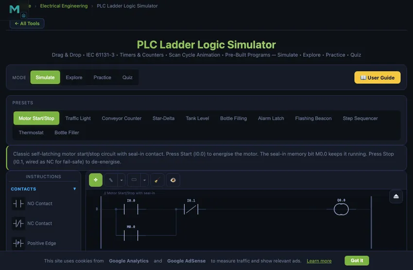
Select instructions from the collapsible palette on the left. Click an instruction to add it to the currently selected rung, or drag it directly onto the ladder diagram. Use the Add Rung button to insert new rungs. Click Run to start the PLC scan cycle and watch power flow through your logic in real time.
Load a preset program (Motor Start/Stop, Traffic Light, Conveyor Counter, Star-Delta, Tank Level) to instantly study a working ladder diagram. Toggle inputs using the I/O panel below the canvas and observe how outputs respond based on your logic.
3 Instruction Library — 22 IEC 61131-3 Instructions
Contacts (4): Normally Open (NO) contact, Normally Closed (NC) contact, Positive Edge detection (rising edge), Negative Edge detection (falling edge).
Coils (4): Standard output coil, Set (latch) coil, Reset (unlatch) coil, Negated output coil.
Timers (3): TON (on-delay timer), TOF (off-delay timer), TP (pulse timer). All with configurable preset time values.
Counters (2): CTU (count up), CTD (count down). Both with configurable preset values and reset inputs.
Compare (4): EQU (equal), NEQ (not equal), GRT (greater than), LES (less than). Compare register values for conditional logic.
Math (3): MOV (move/copy value), ADD (addition), SUB (subtraction). Perform arithmetic on data registers.
Structure (2): Branch Start (opens parallel OR path), Branch End (closes parallel path). Used to create OR logic in rungs.
4 Building & Simulating Programs
Instructions are organised into collapsible categories in the palette. Click to add to the active rung, or drag onto the canvas. Each rung represents one logic line from the left power rail to the right power rail.
5 Pre-Built Programs: Motor Start/Stop (seal-in circuit), Traffic Light (sequential timer), Conveyor Counter (count and stop), Star-Delta (motor starter with timer), Tank Level (compare and control).
Simulation: Green highlighting shows power flow through energised contacts and coils. The I/O panel provides interactive input toggles and output LED indicators. Readout panel shows scan time, cycle count, active rungs, and memory usage.
Editing: Right-click any instruction to edit its address, delete it, or insert rungs. Use Step mode to execute one scan cycle at a time for debugging. Ctrl+Z to undo.
5 Explore, Practice & Quiz
Explore provides concepts across Fundamentals (scan cycle, memory addressing, data types), Contacts & Coils (NO, NC, latch/unlatch), Timers (TON, TOF, TP applications), Counters (CTU, CTD, cascaded counters), Logic (AND, OR, XOR, seal-in), and Applications (motor control, sequencing, safety circuits).
Practice offers randomised problems on timer calculations, counter presets, Boolean logic evaluation, scan cycle analysis, and addressing with step-by-step solutions.
Quiz tests with 5 randomly selected questions from a pool covering instruction types, timing diagrams, addressing modes, and IEC 61131-3 standards.
6 Keyboard Shortcuts & Tips
Shortcuts: Space = Run/Stop, Ctrl+Z = Undo, Delete = Delete selected, Escape = Cancel.
- Always use a seal-in contact (self-holding circuit) for latching motor starters — this is the fundamental PLC pattern.
- Place stop contacts as NC (normally closed) for fail-safe operation — a broken wire stops the motor.
- Use TON timers for most delay applications; TOF is specifically for keeping outputs on after the input drops.
- Organise your program: inputs at the top, processing in the middle, outputs at the bottom.
- Use Set/Reset coils instead of seal-in circuits when the set and reset conditions are on different rungs.
- Standard IEC addressing: I = Input, Q = Output, M = Memory, T = Timer, C = Counter.
- The PLC processes rungs top to bottom, left to right — rung order matters for outputs that depend on other outputs.
PLC Ladder Logic Simulator — Learn Programmable Logic Controller Programming Online
Why PLCs Are Still Everywhere After 50 Years
Modicon shipped the first PLC in 1968. The control engineering profession has reinvented itself a dozen times since — we now have embedded microcontrollers cheaper than a button, full Linux SBCs in industrial enclosures, and cloud-connected smart sensors with built-in analytics. None of these have displaced PLCs from the factory floor. The reasons are practical, not nostalgic.
PLCs survive because the trade-offs that matter on a factory floor have not changed. They are deterministic: the scan cycle is fixed and known, so timing is repeatable. They are rugged: industrial enclosures rated to IP65 or higher, conformal-coated boards, robust against electrical noise and temperature swings. They are maintainable: a maintenance engineer can read ladder logic without being a software developer, because the diagram looks exactly like the relay-logic circuits the same engineer trained on. And they are certifiable: safety-rated PLCs (SIL2, SIL3) have a regulatory pedigree that no general-purpose microcontroller offers.
The Seal-In Circuit — The First Pattern Every PLC Programmer Learns
Every PLC course starts with the same example: a motor that should start when the Start button is pressed and keep running until Stop is pressed. The naive ladder — start button contact in series with motor coil — only runs the motor while the button is held. Release the button, motor stops. Useless.
The fix is the seal-in (latching) circuit. In parallel with the Start button contact, add a normally-open contact from the motor output coil. When Start is pressed, the motor coil energises; that energises the output bit, which closes the parallel contact, which keeps the rung TRUE even after the Start button is released. The Stop button (normally-closed contact, in series) breaks the rung and de-energises the coil, ending the latch.
This single pattern — coil contact in parallel with start, NC stop in series — underlies every motor starter, conveyor-belt run command, lighting control, and pump start logic in industry. Once you internalise it, the rest of PLC programming is variations on the theme.
Timer Use Cases That Show Up in Every Real Program
- Bottle-filling line. Sensor detects bottle, TON timer holds the fill valve open for 2 seconds. After preset, valve closes, bottle moves on. Adjusting the preset adjusts the fill volume.
- Conveyor belt anti-jam. If conveyor runs for more than 30 seconds without a part-detected sensor pulse, TON triggers a fault output and stops the line. Manual reset required.
- Air-compressor off-delay. Pressure switch triggers compressor start. TOF timer keeps the cooling fan running for 60 seconds after the compressor stops, so heat dissipates before the fan shuts off.
- Flashing fault indicator. Pair of TON timers driving an oscillator: when fault active, light flashes at 1 Hz. The same pattern in software that a 555 timer chip would do in hardware.
References for PLC Programming
- IEC 61131-3:2013 — Programmable controllers — Part 3: Programming languages. The defining standard for ladder logic, structured text, and the other four IEC languages.
- Petruzella, F. D. — Programmable Logic Controllers, 5th ed. The widely-used vocational textbook.
- Bolton, W. — Programmable Logic Controllers, 6th ed. The mechanical-engineer-friendly introduction.
- Siemens, Rockwell, Mitsubishi PLC programming manuals — freely available online. Each vendor has its own dialect of IEC 61131-3, but the core is portable.
A Programmable Logic Controller (PLC) is the backbone of modern industrial automation. From manufacturing assembly lines to water treatment plants, PLCs execute control logic that keeps processes running safely and efficiently. Ladder logic, defined in the IEC 61131-3 standard, remains the most widely used PLC programming language worldwide. This free simulator lets you build ladder diagrams with 22 instruction types, simulate scan cycles in real time, and master PLC programming through hands-on practice.
This free PLC ladder logic simulator provides a complete virtual PLC environment directly in your browser. Using standard IEC 61131-3 instruction symbols, you can place contacts, coils, timers, counters, compare blocks, and math instructions onto ladder rungs and observe real-time scan cycle execution. Toggle digital inputs, watch output LEDs respond, and learn how industrial automation programs work through interactive experimentation. Whether you are preparing for a Siemens, Allen-Bradley, or Mitsubishi PLC certification, the fundamental ladder logic concepts are universal and transferable across all PLC brands.
Understanding the PLC Scan Cycle
Every PLC operates in a continuous scan cycle consisting of three phases. First, the Input Scan reads all physical inputs (pushbuttons, sensors, limit switches) and stores their states in an input image table in memory. Second, the Program Scan executes the ladder logic program from the first rung to the last, evaluating each contact condition and updating coil states in an output image table. Third, the Output Scan transfers the output image table values to the physical output modules (motor contactors, solenoid valves, indicator lights). A typical scan cycle takes 1 to 10 milliseconds depending on program size and CPU speed. This cyclic operation ensures deterministic, repeatable behaviour essential for industrial process control.
Contacts and Coils — The Building Blocks
In ladder logic, contacts represent input conditions and coils represent output actions. A Normally Open (NO) contact passes power when its associated address is TRUE (energised). A Normally Closed (NC) contact passes power when its address is FALSE (de-energised) — this is essential for emergency stop circuits where a broken wire must stop the machine. Contacts arranged in series create AND logic (all must be true), while contacts on parallel branches create OR logic (any can be true). The seal-in circuit, where an output coil’s own NO contact is placed in parallel with the start button, is the most fundamental PLC pattern — equivalent to a relay self-holding circuit.
Timers and Counters in PLC Programming
Timers introduce time-based control into ladder programs. The TON (On-Delay Timer) is the most common: it starts timing when its input goes TRUE and energises its output bit after the preset time elapses. If the input drops before the preset, the timer resets to zero. The TOF (Off-Delay Timer) passes the input signal immediately and keeps the output energised for the preset duration after the input turns OFF — useful for cooling fans that must run after a motor stops. The TP (Pulse Timer) generates a fixed-width output pulse on each rising edge of its input, regardless of input duration. Counters track events: CTU (Count Up) increments on each rising edge of its count input and sets its output when the accumulated value reaches the preset. CTD (Count Down) decrements from a preset value and sets its output when reaching zero.
IEC 61131-3 Addressing and Data Types
The IEC 61131-3 standard defines a consistent addressing scheme used across PLC manufacturers. I (or %I) prefixes denote physical inputs, Q (or %Q) denotes physical outputs, and M (or %M) denotes internal memory bits (markers). Byte-level addressing uses the format I0.0 where the first number is the byte address and the second is the bit within that byte (0–7). Word registers such as MW0, MW2 store 16-bit integer values for timer presets, counter values, and arithmetic operations. Understanding this addressing scheme is essential for writing structured, maintainable PLC programs across Siemens S7, Allen-Bradley CompactLogix, Mitsubishi FX, and other platforms.
Common PLC Ladder Logic Instruction Reference
| Instruction | Symbol | Function |
|---|---|---|
| NO Contact | ─] [─ | Passes power when address bit is TRUE |
| NC Contact | ─]/[─ | Passes power when address bit is FALSE |
| Output Coil | ─( )─ | Energises output when rung has power flow |
| Set (Latch) | ─(S)─ | Latches output ON; stays ON until Reset |
| Reset (Unlatch) | ─(R)─ | Resets a latched output to OFF |
| TON Timer | [TON] | On-delay: output after preset time elapsed |
| TOF Timer | [TOF] | Off-delay: output stays on after input drops |
| CTU Counter | [CTU] | Counts up on rising edge, output at preset |
| CTD Counter | [CTD] | Counts down from preset, output at zero |
| EQU Compare | [EQU] | TRUE when source A equals source B |
Who Uses This PLC Ladder Logic Simulator?
This PLC training simulator is designed for Technical and Vocational Education and Training (TVET) students studying industrial automation, electrical engineering, and mechatronics. Vocational instructors use it as a classroom teaching aid to demonstrate ladder logic concepts before students work on physical PLC trainers. Maintenance electricians use it to practice troubleshooting and understand existing plant programs. Automation engineers prototype control sequences before downloading to actual PLCs. The four learning modes (Simulate, Explore, Practice, Quiz) provide a complete educational progression from theory to hands-on application, making it an ideal free PLC programming trainer for learners at any level.
Explore Related Simulators
If you found this PLC ladder logic simulator helpful, explore our Electro-Pneumatic Circuit Simulator, Pneumatic Circuit Simulator, DC Motor Simulator, and Diode & Rectifier Simulator for more hands-on practice.