
Induction Motor Simulator & AC Motor Virtual Lab
Free online induction motor simulator for three-phase and single-phase AC machines — watch the rotor slip behind the rotating field, plot the torque-slip characteristic, run no-load, blocked-rotor and load tests, extract the equivalent circuit, and compare star-delta against direct-on-line starting. Simulate · Explore · Practice · Quiz

Display Controls
📚 Learning panels
Σ Live equations — values substituted from the current state
⚡ Power flow & losses
💡 What this machine is telling you
1 Overview
The Induction Motor Simulator is a working AC machines laboratory. It models ten three-phase machines from 0.75 kW to 160 kW and four single-phase machines, each solved from its equivalent circuit, and every nameplate figure you see is solved from that circuit rather than typed in. A machine that could not reach its rated output would fail the build.
Four modes sit along the top. Simulate is the workspace: a cutaway machine or a full test bench, live readouts, and six characteristic graphs. Explore is a card deck of the underlying concepts. Practice generates worked problems. Quiz scores you on them.
It is built for electrical and mechanical engineering students, instructors running an AC machines lab, and technicians who want the feel of a brake test without a bench.
2 Pick a machine and load it up
The MACHINE selector holds the catalogue. Start with the 5.5 kW, 400 V, 4-pole machine: it is the ordinary industrial workhorse and every other machine reads as a variation on it. CONNECTION forces star or delta instead of the machine's rated connection.
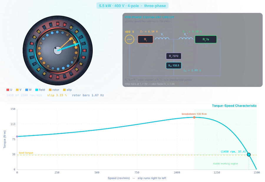
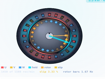
Drag the Load torque slider. The rotating field keeps turning at synchronous speed while the rotor falls further behind — that growing gap is the slip, and it is what generates rotor current and therefore torque. Push past the breakdown torque and the machine stalls, because beyond that point more slip gives less torque.
Torque follows the square of the applied voltage, so a 10 per cent supply dip costs 19 per cent of the torque. Frequency changes the synchronous speed directly (Ns = 120f/P). Hold V/f constant and the whole curve slides sideways at almost constant height — that is exactly what a variable-frequency drive does. Note the frequency slider changes the supply, not the design: feed a 50 Hz machine at 400 Hz and it really does see eight times the per-unit reactance.
Every slider has a stepper box beside it — type an exact value instead of dragging. The boxes are unit-aware, so in Imperial mode you can enter lbf·ft directly.
3 The two canvas views
The VIEW switch in the top-left corner of the canvas swaps between two pictures of the same machine.
Machine is the cutaway with the live equivalent circuit — what the motor is. The field is painted through the stator teeth and the air gap where the flux actually runs: on a three-phase machine it travels at synchronous speed, and on a single-phase machine it stands still and pulsates, which is drawn as the standing resultant plus the two counter-rotating halves it resolves into. That is the whole reason a single-phase machine has no starting torque, and single-phase machines get the double revolving-field circuit to match, not the three-phase one.
Test Bench is the laboratory: a three-phase supply through a variac and a star-delta starter, an instrument cluster, the motor bolted to a bedplate with a rotor-lock pin, and a rope-brake dynamometer — a water-cooled brake drum on the shaft with a rope over it, a spring balance on each end reading in kilograms, and a loading handwheel under each. The bench works the standard brake test live: R = (D+d)/2, T = (S₁ − S₂) × 9.81 × R, P = 2πNT/60, η = P/(W₁+W₂).
Watch the two balances as you load the machine: their difference grows but their sum never changes. A rope is inextensible, so the tight side gains exactly what the slack side loses — and past the capstan limit S₁/S₂ = eμθ the rope slips and the rig says so.
Note there are two wattmeters, because that is how three-phase power is measured on a three-wire supply. Their sum is the total power, and their ratio gives the power factor. Run the no-load test and watch W₂ go negative — that is not a fault, it is what happens whenever the power factor falls below 0.5, and it is the classic thing this method demonstrates.
The Display Controls chip in the top-right corner of the canvas turns the field vector, flux, rotor-bar currents, slip marker, labels and the operating-point marker on and off independently. Your choices are remembered between visits.
4 Load Test — running a standard experiment
Load Test opens the procedure picker. Each one runs as a timed sequence on the bench: the variac winds, the lock pin drops, the brake tightens, the needles swing and settle, and each reading is written onto the observation sheet as it is taken. A progress banner names the step you are watching, and you can cancel at any point. Nothing is scripted — every reading comes from the same solved model that drives the live readouts, so a test result and the simulator can never disagree. When a test finishes, the result opens with an Export Report button in it.
- No-load test — uncoupled at rated volts, repeated at falling voltage. Extrapolating the no-load power to zero volts separates core loss from friction and windage, because core loss follows V² while friction does not.
- Blocked-rotor test — shaft locked, voltage raised until rated current flows. Gives rotor resistance and total leakage reactance. Run it at rated frequency and at 25 per cent, and compare: the difference is rotor bar skin effect, and it is why IEEE 112 asks for the reduced-frequency version.
- DC test — stator resistance. Watch the connection factor: a star winding puts two phases in series across the meter, a delta winding puts one in parallel with two.
- Load test — the full characteristic, walked down with the rope brake.
- Starting methods — direct-on-line against star-delta, autotransformer taps and, on the wound-rotor machine, external rotor resistance.
Parameter extraction combines the first three into a full equivalent circuit, then shows it beside the true values so you can see which elements the standard method recovers well and which it only estimates.
5 Machine Condition — putting a fault on the machine
A load test is a diagnostic. With every machine healthy all the procedures agree and you never find out what they are for, so the CONDITION selector puts a single realistic fault on the same nameplate — a stator winding fault, worn bearings, shorted laminations, an eccentric air gap, or broken rotor bars. Each one leaves its fingerprint on a different measurement:
| Fault | DC test (R₁) | No-load intercept | No-load slope | No-load current | Blocked rotor (R₂) |
|---|---|---|---|---|---|
| Stator winding fault | 1.90× | 1.00× | 1.01× | 1.00× | 1.00× |
| Worn bearings | 1.00× | 3.19× | 1.02× | 1.00× | 1.00× |
| Shorted laminations | 1.00× | 1.00× | 2.47× | 1.00× | 1.00× |
| Eccentric air gap | 1.00× | 1.00× | 0.99× | 1.37× | 0.97× |
| Broken rotor bars | 1.00× | 1.00× | 1.00× | 1.00× | 1.57× |
Worn bearings and shorted laminations both raise the no-load power, and only running that test at several voltages separates them: friction does not care about voltage so it lands in the intercept, while core loss follows V² and lands in the slope. That is exactly why the standard asks for the multi-voltage version, and it is why no single test identifies a fault — the set of them does.
Diagnose reads the verdict back out of the measurements, never from the setting. Set a fault, run the tests, and see whether you would have caught it. Load percentages always reference the sound machine, or "100 % load" would mean a different torque under every fault.
6 Reading the six graphs
The GRAPH switch under the plot changes what is drawn there.
- Torque-Slip — the characteristic itself, plotted against speed because that is how a machine is used, with your operating point, the breakdown point and the stable working region marked.
- Current & PF — why a lightly loaded motor has such a poor power factor.
- Power Flow — the loss ledger from input to shaft, stage by stage.
- Efficiency — the peak sits below full load, where copper loss has grown to equal the fixed iron loss.
- Starting Methods — torque against inrush for every starter, so the cost of each is visible.
- V/f Control — the curve overlaid at several frequencies.
7 Learning panels & Calculations
Below the controls, three panels open on demand. Live equations shows the formulas with the current numbers substituted, so you can follow the arithmetic rather than trust it. Power flow & losses itemises where every watt goes. What this machine is telling you reads the present operating point and says what it means — a stalled machine, a badly derated supply, a single-phase machine dragging its backward field.
The Σ Calculations button opens the same working in full, step by step from supply voltage to shaft output.
8 Explore, Practice & Quiz
Explore is a deck of concept cards in six categories — Basics, Formulas, Testing, Starting, Single-Phase and Standards — each with a diagram and the formula that goes with it. Use it when a term on the canvas is unfamiliar.
Practice generates fresh numerical problems from twelve generators, each one re-derived from the numbers its own prompt states. Answer, then check — the worked solution is shown either way.
Quiz scores you across the whole topic and shows the reasoning behind every answer at the end.
9 Units, export & keyboard
SI / Imperial switches torque to lbf·ft and power to horsepower throughout — readouts, canvas, graphs, practice problems and the report. Volts, amps, hertz and per cent are the same in both systems. The choice is remembered between visits.
Report produces a printable laboratory report with the machine data, the readings taken, the calculations and the resulting characteristic — the document you would hand in. It pulses once a test finishes, because that is when it first has something new in it. CSV exports the swept curve for plotting elsewhere, and PNG saves the canvas.
Keyboard: Space pause or resume · ← → adjust load · R reset · Esc close a dialog. Right-click the canvas for save, copy readings and reset.
10 How the numbers are checked
Every figure this tool reports is checked against an independently written reference model before release: the app solves the circuit from the supply inward, the verifier re-derives it from a Thevenin source, and agreement means the physics is right rather than that one bug is spelled twice.
The suite runs 256,281 assertions over 11,470 operating states — power balance and P_ag = Tωs to double precision, rotor-bar skin effect against an independent implementation of Field's factors, star-delta giving exactly one third (not 1/√3), breakdown torque independent of rotor resistance while its slip moves, and single-phase starting torque coming out exactly zero from the algebra rather than being special-cased. Every nameplate is asserted to sit inside the IEC 60034-30-1 and NEMA MG 1 realism bands, and an 8,064-point audit checks that no setting can produce an impossible value — efficiency above 100 %, a power factor outside ±1, output above input, a negative loss or a rotor above synchronous speed.
Understanding the Induction Motor — a Free Interactive AC Motor Simulator
The three-phase induction motor turns roughly half the electrical energy generated on earth into mechanical work. It has no brushes, no commutator and no electrical connection to its rotor at all: the rotor current is induced, exactly as it is in the secondary of a transformer, which is why the machine is sometimes called a rotating transformer. This induction motor simulator solves the per-phase equivalent circuit in your browser, so every number on the screen — speed, slip, current, power factor, efficiency, torque — comes from one consistent solution rather than from a set of formulas that disagree at the edges.
Slip: why an induction motor can never reach synchronous speed
Three windings spaced 120° apart, carrying currents 120° apart in time, produce a magnetic field that rotates at the synchronous speed
Ns = 120 × f / P
where f is the supply frequency in hertz and P the number of poles. At 50 Hz a 2-pole machine gives 3000 rev/min, a 4-pole 1500, a 6-pole 1000 and an 8-pole 750. At 60 Hz those become 3600, 1800, 1200 and 900.
The rotor cannot turn at that speed. If it did, it would be moving with the field, no flux would cut the rotor bars, no EMF would be induced, no current would flow and no torque would be produced — the machine would immediately slow down. So the rotor always runs slightly behind, and the fractional lag is the slip:
s = (Ns − N) / Ns
Full-load slip is not a constant of nature; it falls steadily with machine size, because larger machines have proportionally lower rotor resistance. In the simulator's own catalogue:
| Rating | Full-load speed | Slip | Line current | Power factor | Efficiency |
|---|---|---|---|---|---|
| 0.75 kW | 1404 rev/min | 6.4 % | 1.65 A | 0.79 | 82.6 % |
| 5.5 kW | 1450 rev/min | 3.3 % | 10.7 A | 0.83 | 89.6 % |
| 11 kW (2-pole) | 2920 rev/min | 2.7 % | 19.7 A | 0.88 | 91.4 % |
| 15 kW (8-pole) | 730 rev/min | 2.7 % | 30.5 A | 0.78 | 91.0 % |
| 75 kW | 1480 rev/min | 1.3 % | 131 A | 0.87 | 95.0 % |
| 160 kW (3.3 kV, 6-pole) | 989 rev/min | 1.1 % | 35.0 A | 0.84 | 95.4 % |
Two trends are worth pausing on. Efficiency climbs with size, from 82.6 per cent to over 95. And the 8-pole machine has a distinctly worse power factor than the 2-pole one at similar power, because a slow machine needs more magnetising current for the same output — a real design penalty that catches people out when they specify low-speed drives.
The torque-slip characteristic
Applying Thevenin's theorem to the equivalent circuit gives the torque at any slip:
T = (3 / ωs) × Vth² × (R₂/s) / [ (Rth + R₂/s)² + (Xth + X₂)² ]
The shape that falls out of this has three landmarks. Starting torque at s = 1. Breakdown torque, the maximum the machine can ever produce, at the slip
smaxT = R₂ / √(Rth² + (Xth + X₂)²)
and the near-straight working region between breakdown and synchronous speed, where the machine actually operates and where speed falls almost linearly with load.
Notice what is missing from the breakdown-torque expression: rotor resistance appears in the slip at which the peak occurs, but not in its height. Adding resistance to the rotor slides the peak towards standstill without changing how large it is. That single fact is the entire basis of wound-rotor starting, and you can watch it happen on the slip-ring machine in the simulator — the peak marches from 17 per cent slip out to 92 per cent while its height stays at 684 N·m.
Torque also follows the square of the applied voltage. A supply sagging to 90 per cent delivers only 81 per cent of the torque, which is why a heavily loaded motor on a weak supply can stall on a voltage dip that the lights barely register.
Why deep rotor bars exist: the skin effect that makes motors start
Here is a puzzle that a constant-parameter model cannot solve. Full-load slip on a 75 kW motor is about 1.3 per cent, which demands a very low rotor resistance. But low rotor resistance puts the breakdown torque close to synchronous speed and leaves almost nothing at standstill — on paper such a machine develops well under half its rated torque at start, and could not accelerate its own fan.
Real machines escape this by making the rotor resistance depend on speed. Rotor current frequency is s × f, so at standstill the bars carry full line frequency and the current crowds into the top of each bar; once the machine is up to speed the rotor frequency is only a hertz or two and the current spreads over the whole bar. For a rectangular bar the classical result gives the AC/DC resistance ratio as
kR = ξ (sinh 2ξ + sin 2ξ) / (cosh 2ξ − cos 2ξ), with ξ = h / δ
where h is the bar height and δ the skin depth. Because ξ scales with √(s f), a deep-bar rotor is high-resistance while starting and low-resistance while running — which is exactly what is wanted. This simulator models that effect explicitly, which is why its large machines start properly instead of collapsing at standstill, and it is also what the NEMA design letters physically describe.
| Design | Rotor construction | Starting torque | Starting current | Full-load slip | Typical use |
|---|---|---|---|---|---|
| A | Shallow bar, low resistance | Normal | High | Low, under 3 % | Machine tools where inrush is not restricted |
| B | Deeper bar, moderate skin effect | 1.5–2.5 × FLT | 5.5–7.5 × FLC | Under 5 % | The general-purpose default: fans, pumps, compressors |
| C | Double cage | 2.0–2.5 × FLT | Normal | Under 5 % | Loaded conveyors, crushers, piston pumps |
| D | Shallow, high-resistance bar | 2.75 × FLT and above | Low | 5–13 % | Punch presses, shears, hoists — flywheel loads |
| Wound | Wire-wound rotor, slip rings | Set by external resistance | Set by external resistance | Under 5 % | Cranes, mills, high-inertia starts |
No-load and blocked-rotor tests: finding the equivalent circuit
The equivalent circuit is not something you can measure directly. It is reconstructed from three terminal tests, and the no load and blocked rotor test pair is a standard laboratory exercise in every machines course.
The DC test gives stator resistance. Take care with the connection: applying DC across two terminals of a star winding puts two phases in series, so R₁ = V/2I, while on a delta winding it puts one phase in parallel with two in series, so R₁ = 1.5 V/I. Getting that factor wrong scales every copper-loss figure that follows.
The no-load test runs the machine uncoupled at rated voltage. Slip is almost zero, so R₂/s is enormous and the rotor branch is effectively open; what remains is the magnetising branch, the core loss, and friction and windage. Repeating the test at falling voltage and extrapolating the input power back to zero volts separates the last two, because core loss falls as V² while friction and windage does not change. In the simulator that extrapolation recovers the true friction-and-windage figure to within about two per cent.
The blocked-rotor test locks the shaft and raises the voltage until rated current flows. With s = 1 the rotor branch dominates and the magnetising branch can be neglected, giving rotor resistance and total leakage reactance. IEEE 112 specifies about 25 per cent of rated frequency for this test, and the reason is the skin effect described above: run it at full frequency on a deep-bar rotor and the rotor resistance reads far higher than its running value, describing a machine that does not exist above standstill. Run both versions in the simulator and compare the error — the standard exists for a measurable reason.
One caveat the textbooks are honest about and worth repeating: the split of leakage reactance between stator and rotor is not measurable. It is assigned from the design class, and that assumption is the largest single source of error in the whole procedure.
Starting an induction motor: why the inrush matters
At standstill the machine is a short-circuited transformer, and it draws five to seven times full-load current. On a small motor nobody notices. On a large one the volt-drop dims every light on the feeder, so supply authorities set limits and reduced-voltage starting becomes compulsory. Every reduced-voltage method obeys the same square law, because both torque and current scale with the square of the winding voltage.
| Method | Line current | Starting torque | Notes |
|---|---|---|---|
| Direct on line (DOL) | 100 % | 100 % | Simplest and cheapest; harsh on the supply and the driven machine |
| Star-delta | 33 % | 33 % | Only for delta-wound motors that can start unloaded; a current surge occurs at changeover |
| Autotransformer 80 % tap | 64 % | 64 % | Tap selectable; more expensive, but torque per ampere is better than a series reactor |
| Autotransformer 65 % tap | 42 % | 42 % | |
| Autotransformer 50 % tap | 25 % | 25 % | |
| Rotor resistance (wound rotor only) | Reduced | Increased | The only method that raises torque while cutting current — hence its survival on cranes and mills |
Star-delta deserves its own sentence, because the factor of three surprises people who expect √3. Reconnecting a delta winding into star drops each winding's voltage by √3, so winding current falls by √3. But in delta the line current was √3 times the winding current, whereas in star they are equal. The two factors multiply and the line current falls to a third. Torque, following voltage squared, also falls to a third. You can verify both on screen: the simulator computes them from the circuit rather than applying a rule of thumb.
Single-phase induction motors: the machine that cannot start itself
A single-phase winding does not produce a rotating field. It produces a pulsating one, which by simple trigonometry is identical to two fields of half amplitude rotating in opposite directions. The rotor sees slip s against the forward field and 2 − s against the backward one, and the net torque is the difference between what the two produce.
At standstill s = 1, so both fields present the rotor with exactly the same slip, the two torques are identical, and they cancel. A single-phase induction motor has precisely zero starting torque. Give the shaft a spin in either direction and it will run up in that direction, which is the classic lecture demonstration. In this simulator that zero is not a special case written into the code — it emerges from the algebra, and the verification suite asserts it.
Every practical single-phase motor therefore carries a second winding, displaced in space and fed with a current displaced in time. The rotating component of the field goes as Imain × Iaux × sinα, where α is the phase angle between the two currents, and the different ways of producing that angle define the motor types:
| Type | How the phase split is made | Starting torque | Efficiency | Typical application |
|---|---|---|---|---|
| Capacitor-start | Electrolytic capacitor in the auxiliary winding, switched out at ~75 % speed | 3.5 × FLT | ~74 % | Compressors, pumps, small machine tools |
| Split-phase | Auxiliary winding simply wound more resistive — about 25° of split | 1.8 × FLT | ~60 % | Fans, small grinders, belt-driven blowers |
| PSC (permanent split capacitor) | Small run capacitor stays in circuit permanently | 0.45 × FLT | ~59 % | Ceiling fans, fan-coil units — anything starting unloaded |
| Shaded pole | Shorted copper ring drags the flux across part of each pole | 0.40 × FLT | ~27 % | Microwave and refrigerator fans |
The permanent split capacitor is the instructive case. Its starting torque is feeble not because its phase split is poor — the capacitor gives an excellent angle — but because a small run capacitor passes very little current. Keeping that capacitor in circuit while running is what gives the PSC its good power factor, around 0.80 against 0.60 for a split-phase machine of similar size.
Who uses this simulator?
- Electrical engineering students preparing an AC machines laboratory, or checking a torque-slip calculation before the viva.
- Technical and vocational trainees who need to see why a motor draws six times its rated current at switch-on before they wire a star-delta starter.
- Lecturers and lab instructors demonstrating no-load and blocked-rotor tests when the laboratory machine is in use, or showing a stall without damaging hardware.
- Maintenance and plant technicians reasoning about why a motor runs hot, starts slowly, or trips on a voltage dip.
- Design and application engineers comparing NEMA design classes, or checking whether star-delta starting will actually accelerate a given load.
Explore Related Simulators
Induction machines sit inside a family. The AC Generator Simulator covers the same rotating field from the generating side, with the EMF equation and alternator characteristics. The Star-Delta Connection Simulator works through the line and phase relationships that make star-delta starting give exactly one third. The Transformer Simulator shares this machine's equivalent circuit almost element for element — an induction motor really is a rotating transformer with a short-circuited secondary. And the DC Motor Simulator & Load Test Lab runs the same style of laboratory procedure on a DC machine, where speed control is easy and starting is the hard part — the mirror image of the trade-off here. Starting and sequencing that machine is a control problem rather than a machine one, and the PLC Ladder Logic Simulator is where those start, stop and interlock rungs get written.
Updated