How a Hydraulic Brake System Works: From Master Cylinder to Wheels
A hydraulic brake system turns a modest push on a pedal or lever into tens of kilonewtons of clamp force at the wheels. It does it with a closed circuit of brake fluid: a small master cylinder piston raises the pressure, and by Pascal’s law the same pressure acts on the much larger pistons in the calipers and wheel cylinders. This simulator shows the whole chain moving, for a single-wheel rig, a motorcycle and a car, and lets you change every factor that decides how well it stops.
The braking sequence, step by step
- The pedal, a lever with a ratio of about 3 to 5, multiplies the foot force onto the pushrod.
- In a car the vacuum booster adds its assist, several times the driver’s input, until it reaches runout.
- The master piston moves about a millimetre and its cup seal covers the compensating port. The chamber is now sealed from the reservoir.
- Fluid is pushed down the lines while the caliper pistons take up their running clearance. The pressure stays low.
- The pads touch the disc (or the shoes the drum). Now very little fluid moves and the pressure climbs along the rest of the pedal stroke.
- Each wheel’s brake makes a friction torque; the tyres push back on the road and the vehicle slows.
- On release the springs return the master piston, the port reopens, and the square-cut caliper seals pull the pistons back.
Brake force calculation: pedal to tyre
The force is multiplied in stages. For the default car in the simulator (250 N on a 3.8 : 1 pedal, a 9-inch booster with a boost ratio of 4.5, a 22.2 mm tandem master cylinder, 54 mm floating calipers on 280 mm discs with semi-metallic pads, 228 mm rear drums with 19.05 mm wheel cylinders and a proportioning valve with a 35 bar knee):
| Stage | Formula | Default car |
|---|---|---|
| Pushrod force | F × pedal ratio | 950 N |
| Booster output | Fin + min[(B − 1)Fin, Δp·A] | 3,226 N (at runout) |
| Line pressure | p = F/Am | 83.3 bar |
| Front clamp force | N = p·Apiston | 19.1 kN |
| Front brake torque | T = 2μ·N·reff | 1,840 N·m per wheel |
| Rear pressure after the valve | pk + 0.3(p − pk) | 49.5 bar |
| Rear drum torque | T = C*·p·Awc·r | 373 N·m per wheel |
| Front share of braking | Ffront/Ftotal | 83 % |
| Stopping distance from 100 km/h | 1 s reaction + braking | 67.3 m |
A smaller master cylinder bore raises the pressure for the same foot force but needs more pedal travel; larger caliper pistons raise the clamp force but take more fluid. Those two trade-offs, force against travel, are what a brake designer balances.
Disc brakes vs drum brakes
A disc brake squeezes the disc between two pads, so the friction force is 2μ times the clamp force (about 0.8). A drum brake pushes its shoes outward, and friction drags the leading shoe harder into the drum: a simplex drum reaches a brake factor near 2. That self-energising action makes drums powerful and cheap, but very sensitive to friction: with organic linings at 500 °C the single-wheel rig’s drum loses about 45 % of its torque while the disc loses about 36 %. Discs also cool and shed water better, which is why they are fitted at the front, where most of the braking is done.
Load transfer, brake distribution and ABS
When a vehicle decelerates its weight shifts forward by m·a·h/L. The front axle can then take more braking force and the rear less, so the ideal split between the axles changes with the deceleration (a parabola on the Diagram view). If the rear brakes are too strong the rear wheels lock first and a car spins; a proportioning valve limits the rear pressure above a knee. ABS goes further: it releases and re-applies each wheel’s pressure several times a second to keep the tyre near its peak grip. On a motorcycle the transfer is so large that the rear wheel lifts once the deceleration exceeds g×xf/h; with the default bike the front brake alone stops it from 80 km/h in 49.9 m, the rear alone needs 96.1 m.
What goes wrong: what-if results for the default car
| Change | Line pressure | Stopping distance from 100 km/h |
|---|---|---|
| None (default) | 83.3 bar | 67.3 m |
| Engine off: no booster vacuum | 24.5 bar | 141.4 m |
| Primary circuit leaks, front/rear split | 0 / 83.3 bar | 237.8 m (rear brakes only) |
| Primary circuit leaks, diagonal split | 0 / 83.3 bar | 115.3 m (one front, one rear) |
| 4 cm³ of air in the primary circuit | 54.0 / 83.3 bar (master bottomed) | 81.6 m |
| Pads at 600 °C (fade) | 83.3 bar | 79.6 m |
| Wet road, ABS on | 83.3 bar | 87.5 m |
| Wet road, ABS off (front wheels lock) | 83.3 bar | 100.5 m |
Each row is one click in the simulator. Air in the lines is especially instructive: it compresses by Boyle’s law, so the master cylinder runs out of stroke before the pedal force can be turned into pressure. That is the spongy pedal of an unbled system.
Who uses this simulator?
Automotive and mechanical engineering students studying vehicle brake systems, brake force calculation and brake distribution; vocational and diploma learners working on master cylinders, calipers, drums and bleeding; teachers who want to show the sequence of a hydraulic brake on a projector, slowed down; and anyone who wants to see why ABS, a proportioning valve or a tandem master cylinder exists.
Frequently asked questions
How does a hydraulic brake system work?
The pedal pushes a piston in the master cylinder. Once its seal has covered the compensating port, the chamber is sealed and the piston displaces brake fluid down the lines. The caliper or wheel-cylinder pistons first take up their small running clearance, then the pads or shoes touch and the pressure rises. By Pascal's law that pressure is the same at every wheel of the circuit, and each piston pushes with pressure times its own area, so a small force on a small master piston becomes a large clamp force at the wheels.
How do you calculate brake force from pedal force?
Multiply the pedal force by the pedal ratio to get the pushrod force, add the booster's assist, and divide by the master cylinder area to get the line pressure p. The clamp force at a disc is p times the piston area on one side, the brake torque is 2μ times that clamp force times the effective pad radius, and the force at the tyre is the torque divided by the tyre's rolling radius.
What does a tandem master cylinder do?
It has two pistons in one bore, each feeding a separate brake circuit, either front and rear (II split) or diagonally (X split). Both chambers carry the same pressure. If one circuit leaks, the pedal travels further while that piston bottoms, and then the other circuit still brakes the car.
Why does air in the brake lines make the pedal spongy?
Brake fluid hardly compresses, but air does: by Boyle's law its volume shrinks as the pressure rises, so the master cylinder must push in extra fluid before the pressure builds. The pedal travels further for the same braking, and with enough air the piston reaches the end of its stroke and the pedal goes to the floor.
Why do the rear wheels lock if the rear brakes are too strong?
Braking transfers load from the rear axle to the front by m·a·h/L, so the harder the car stops the less braking force the rear tyres can carry. A proportioning valve reduces the rise of rear pressure above a knee point so the rear wheels do not lock first, which would make the car spin.
Explore Related Simulators
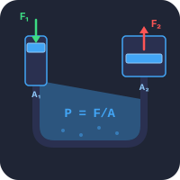
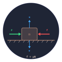
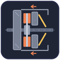
The force multiplication of a brake is Pascal’s law, shown on its own in the Pascal’s Law Simulator; the cylinder itself is sized in the Hydraulic Cylinder Calculator. The grip between tyre and road, and the stopping distance on a slope, are in the Friction & Contact Forces simulator. The other friction device in the driveline is the Clutch System Simulator, and the force that stops the car is Newton’s second law, explored in the Newton’s Laws simulator.
Updated