Vernier Caliper Simulator
Interactive precision measurement trainer
1 Overview
This vernier caliper simulator is a free online tool that lets you practise reading vernier caliper scales in a realistic, interactive environment. It supports both SI (metric) and Imperial (inch) calipers as fully independent instruments. In SI mode, choose between three precision levels: 0.02 mm, 0.05 mm, and 0.1 mm least count. Imperial mode offers two real inch instruments: the decimal caliper (0.001″, 25 vernier divisions on a 40ths beam) and the fractional caliper (1/128″, 8 vernier divisions on a 16ths beam) that reads out in fractions. Four modes — Simulate, Explore, Practice, and Quiz — guide you from learning theory to hands-on measurement mastery.
2 Setting the Zero

When the page loads you are in Simulate mode with SI units and 0.02 mm precision selected. To begin:
- Drag the sliding jaw left or right to set any measurement. You can also use the left/right arrow keys for fine step adjustment.
- Watch the readout badges and info row below the caliper update in real time — they show the reading, MSR, VSR, LC, and the full TR formula.
- Switch precision using the Precision (LC) pills: choose 0.05 mm, 0.02 mm, or 0.1 mm. In Imperial mode the same pills offer 0.001″ and 1/128″.
- Toggle SI / Imperial to switch between a metric caliper (0–100 mm) and an inch caliper (0–4″). The entire scale redraws with the correct divisions.
- Use the Zoom button to magnify the scale area for easier reading of the vernier coincidence line.
- Switch the beam between mm and cm numbering with the pair of buttons on the canvas toolbar. Real 150 mm calipers are sold engraved both ways — 10 20 30 or 1 2 3 on the same graduation lines — so practise on whichever matches the caliper in your hand. It is display only and changes no reading.
3 Taking a Reading
In Simulate mode the caliper responds freely to your input. Drag the jaw to any position and the digital readout displays the exact measurement. This mode is ideal for exploring how the main scale and vernier scale interact. Observe how changing the jaw position shifts the vernier coincidence line — the golden-highlighted division that aligns perfectly with a main scale graduation. The formula panel breaks down every reading step by step: MSR, VSR, LC, and the final total reading. Audio feedback provides subtle click and tick sounds as you drag. Use this mode to build confidence before moving to Practice.
3b Measuring a Real Object
In Simulate mode, the Measure an object button at the bottom-right of the canvas drops a real workpiece into the jaws. Pick from nine parts — rectangular bar, standing cylinder, lying cylinder, ball bearing, cube block, M12 hex nut, Ø10 drill shank, gauge plate, and a ring/bush measured on the inside jaws.
- Choose a part. It is placed against the fixed jaw and the sliding jaw swings fully open, exactly as you would start a real measurement.
- Drag the sliding jaw left (or press ←, or use Close onto part). The jaws stop dead on the part — they cannot pass through it, whatever you do.
- When both faces make contact the part shows green contact marks, a knock sounds, and the dimension line under it reveals the part's true size.
- Now read the scale as usual: MSR + (VSR × LC).
Orientation matters. The same cylinder appears twice: standing, the jaws close on its diameter; lying down, they span its length. The hex nut must be measured across flats, never corners.
Internal diameters work the other way round. Choose the Ring / bush and it appears at the top of the instrument, sitting over the two upper knife edges, with the inside jaws already shut inside the bore. Now you open the jaws — drag right, press →, or use Open onto bore — until both nibs touch the bore wall and stop. The dimension arrows point outward into the walls, the convention for a hole on an engineering drawing. Because the nibs have a tip radius they cannot quite reach the true diameter, so a caliper reads a bore a few hundredths small; a bore gauge or internal micrometer is the right tool when that matters.
Why the reading may not match the part. The sizes are realistic, not tidy — a 5/8″ bearing ball is 15.88 mm and an M12 nut measures under its 18.00 mm nominal. On a 0.05 mm vernier the ball can only be resolved to 15.90 mm. That gap is the instrument's resolution limit, not a mistake, and the object bar spells it out. Switch to the 0.02 mm scale and it closes. Switch the same ball to the imperial caliper and it reads a clean 0.625″.
Turn Zero Error on while a part is loaded to see the effect that matters most in the workshop: the jaws still stop on the true size, but the scale reads high or low until you apply the correction.
3c “Show me How?” — Guided Reading

The round play button at the bottom-right of the caliper, beside Measure an object, starts a guided reading of whatever is currently on the instrument. It is not a video: every arrow, highlight and count is drawn on the scales themselves, and every number comes from the same calculation the readout tiles use, so it can never show you something the tool does not agree with.
- Step 1 — Main Scale Reading. A measuring line grows along the beam to the vernier zero; a red index line carries that position up through the main scale, and an arrow marks the last graduation it passed. The caption asks you to read it before it tells you the value.
- Step 2 — Find the coinciding line. Each vernier line is ruled out in turn with the amount it misses by, one least count more than its neighbour each time, until one lands dead on. One line past the match is tested too, so you can see the coincidence is unique.
- Step 3 — Count the divisions. The count walks from the vernier zero to that line. The upper box shows how many divisions; the lower box shows what they are worth, one least count at a time.
- Step 4 — Total Reading. The TR card fills in row by row, in the order you would write it.
- Step 5 — Zero error, shown only when the caliper has one.
The view magnifies itself to keep both ends of the reading on screen — on a 50-division scale they can be 49 mm apart — and the MSR and VSR tiles start empty and fill in as the walkthrough derives them, so the answer is never on screen before you have been shown how to get it.
Controls: Space play/pause, →/← next and previous step, Esc to close, or the four buttons on the canvas. Stepping pauses at the start of each step — useful when you are talking a class through one. Touching the jaws, changing precision, switching units or loading a part ends the walkthrough, because the steps were built for the reading that was on the instrument when you started it.
It is hidden in Quiz mode, and in Practice until your answer has been marked: a step-by-step reading of the instrument is exactly the answer you are being asked to produce.
3d Locking Screw & Thumb Roller — the two controls on the instrument
Most of what you do here is drag the sliding jaw. Two parts of the caliper are controls in their own right, and both work on the drawing itself rather than from a panel — they are the same two you would reach for on the bench.
The locking screw
The small knurled screw on top of the sliding head. Click it to clamp the jaws; click it again to release. Locked, it turns gold and carries a padlock, and the Lock button on the canvas toolbar shows the same state — they are one control with two handles, not two settings.
- While it is clamped the jaws will not move, and every attempt says so: the screw flashes, a note appears beside it, and the message is announced to screen readers. A lock that refuses in silence just looks broken.
- Both ways of moving the jaws are refused — dragging and the ← / → arrow keys.
- It releases itself when the tool moves the jaws for you: starting the guided reading, the Play sweep in Practice, or loading a workpiece. A clamp that could deadlock the instrument would be a bug, not a feature.
- It is not remembered between visits, deliberately. Re-opening a caliper whose jaws refuse to move reads as a broken tool rather than as a remembered setting.
Why it exists on a real caliper: lock, withdraw, then read. It kills jaw-pressure drift and parallax error in one move, and it is what lets you carry a setting to a surface plate or transfer it to another gauge.
The thumb roller (fine adjustment)
The knurled wheel under the right-hand end of the sliding head. Dragging the jaw across the beam is fast but coarse — one pixel of hand movement is about 0.19 mm, which is ten divisions on a 0.02 mm caliper — so the roller exists to place the last few divisions:
- Click its left or right half to move exactly one least count. Right opens the jaws, left closes them, the same sense as the arrow keys; the arrow under your pointer blinks so you can see which way before you press.
- Hold it to keep stepping, slowly at first and then faster — the same feel as holding a key on a keyboard. It stops on its own at the end of the travel, and at a workpiece.
- Drag from it for a continuous fine feed, about three screen pixels per division instead of ten divisions per pixel. Dragging anywhere else on the head keeps the fast traverse.
- Scroll the mouse wheel anywhere over the caliper for one division a notch.
The roller is geared to the beam, so it turns whenever the jaws move — including when you drag them, use the arrow keys, or load a part — not only when you touch it.
Why it exists on a real caliper: jaw over-pressure is one of the largest error sources in caliper work, often several times the least count. Driving the head with a thumb on the roller gives light, repeatable contact pressure; shoving the frame does not. Close until the part will just still move under light drag.
3e The 3D View
Press 3D in the caliper’s toolbar (on a phone, the 2D | 3D switch sits just above the instrument). The 3D caliper is the same instrument, not a copy: every reading, grade and walkthrough step comes from the same calculation as the flat view, and the choice is remembered on this device. 2D takes you back.
- Move the jaws: drag the slider, the sliding jaw or the vernier plate. The jaws follow your finger. Drag the knurled thumb roller under the slider for a fine feed (one least count per few pixels), or click it for one least count. Over the slider the mouse wheel moves one least count a notch; anywhere else it scrolls the page. The ←/→ keys work as in 2D.
- Lock: click the knurled locking screw on top of the slider (its slot turns a quarter turn when it is tight).
- Look around: drag the background to orbit, right-drag or Shift-drag to pan, pinch or Ctrl+wheel to zoom.
- Views: 3D opens on the Whole instrument, and so does every new part or question. Reading is square to the scales, Measure — the jaws on the part, a bush cut open on the plane of the knife edges, or a block cut open round the depth rod — and Parallax, with an eye-angle slider and the reading an eye off square would take. Labels names the parts.
- Close-up: with a part loaded, press Close-up for a corner view of the jaws on it while you read the scales; tap the corner view to enlarge it to the Measure view.
In Practice and Quiz the 3D view shows no reading, no gold coincidence line, no dimension and no labels until your answer has been marked. The green contact marks still show, because touching the part is not the answer. If your browser cannot run WebGL the 3D button is disabled and the flat view carries on.
4 How the Scale Works
Explore mode is a reference library of vernier caliper concepts, organised into five categories:
- Parts & Components: An interactive, labelled diagram of the instrument. Hover (or tap) any of the twelve numbered callouts — fixed jaw, sliding jaw, outside jaws, inside jaws, main scale beam, metric graduations, inch scale, vernier scale, vernier zero line, depth rod, thumb roller and locking screw — and the part lights up on the drawing while its description, specifications and workshop tips appear alongside.
- Vernier Types: Standard, Dial, Digital, and Depth vernier calipers — learn the differences, ranges, and applications.
- Least Count: Worked examples for 0.02 mm (50-div), 0.05 mm (20-div), 0.1 mm (10-div), 0.001″ (25-div imperial) and 1/128″ (8-div fractional inch) least counts with the LC formula.
- Zero Error: Learn to identify no error, positive error, and negative error, with correction formulas and step-by-step procedures.
- Reading Method: Step-by-step guide — read MSR, find VSR coincidence, calculate TR, and avoid common errors.
Click any card in the grid to view its detailed information panel below.
5 Practice Readings
Practice mode offers two drills side by side, and starting one ends the other so there is only ever a single target:
- Play / Pause — click Play to animate the caliper, then Pause to freeze it at a random opening. Read the scale and type the total reading.
- Measure an object — loads a random workpiece into the jaws. Drag the sliding jaw (or press ← / →) until it stops on the part, then read the scale. Check stays greyed out until the jaws are genuinely in contact, so you cannot guess your way past the measuring step.
Click Check to mark your answer — instant feedback with sound tells you whether you are correct and only then reveals the part's true size. New starts the next challenge and hands the bar back to the Play drill. Your running score is displayed.
Quiz mode: a sequence of 5 questions, of which at least two are always object-measuring tasks — the rest preset the jaws for you to read. For an object question the part arrives with the jaws thrown open and Submit is locked until you have closed onto it. After all 5, a results panel shows your score with star ratings and a row-by-row breakdown. Retake as often as you like; quizzes work in both SI and Imperial, with or without zero error.
Answering on the fractional caliper. With the 1/128″ pill selected the answer box takes a fraction, because that is how the instrument is read: type 1 43/128, 1-43/128 or 43/128. An unreduced answer is accepted — 1 32/128 is marked correct for 1-1/4″ — and a decimal is accepted too, though it is not how the scale is meant to be written.
Different parts, different sizes. Practice and Quiz draw from a separate set of workpieces to the ones in Simulate, so a size you have already met cannot simply be recalled — it still has to be measured.
6 Understanding the Reading
The vernier caliper reading involves three values:
- MSR (Main Scale Reading): In SI, the last whole millimetre mark to the left of the vernier zero. In Imperial, the last 0.025″ mark to the left — or the last 1/16″ mark on the fractional caliper.
- VSR (Vernier Scale Reading): The vernier division number that aligns exactly with any main scale graduation (shown as the golden tick).
- LC (Least Count): SI: 0.02 mm, 0.05 mm, or 0.1 mm. Imperial: 0.001″ or 1/128″.
SI example: MSR = 23 mm, VSR = 9, LC = 0.05 mm → TR = 23 + (9 × 0.05) = 23.45 mm.
Fractional-inch example: MSR = 1 5/16″, VSR = 3, LC = 1/128″ → TR = 1 40/128 + 3/128 = 1 43/128″.
Imperial example: MSR = 0.900″, VSR = 23, LC = 0.001″ → TR = 0.900 + (23 × 0.001) = 0.923″.
7 SI vs Imperial Caliper
This simulator includes two fully independent instruments:
- SI (Metric): Main scale divided into millimetres (0–100 mm). Vernier: 20, 50, or 10 divisions. Switchable precision via Precision pills.
- Imperial — decimal (0.001″): Main scale in 40ths of an inch (0–4″), 0.025″ per division. Vernier: 25 divisions spanning 24 (0.600″). LC = 0.025″ ÷ 25 = 0.001″.
- Imperial — fractional (1/128″): Main scale in sixteenths of an inch, tick heights stepped 1″ > 1/2″ > 1/4″ > 1/8″ > 1/16″. Vernier: 8 divisions spanning 7 (7/16″). LC = 1/16″ ÷ 8 = 1/128″, and every readout — measurement, MSR, zero error and the answer box — is a reduced fraction such as 1-43/128″.
Toggle between them using the SI / Imperial pills in the controls bar. The entire scale, tick marks, labels, readouts, formula, and practice/quiz answers update automatically.
8 Zero Error Simulation
The Zero Error control in the toolbar is off by default. Switch it On to simulate a miscalibrated caliper, then use the − / + stepper to set the error up to ±5 least-count divisions.
- The simulator treats the canvas reading as the observed value (the value the student reads off the scales). The yellow Zero Error card shows the calibration offset; the green Corrected card shows the true measurement: Corrected = Observed − Zero Error.
- With positive ZE (e.g. +0.06 mm at 0.02 LC), the vernier zero sits to the right of the main-scale zero when the jaws are closed — the 3rd vernier division coincides with a main-scale mark.
- With negative ZE (e.g. −0.06 mm), the vernier zero sits to the left of the main-scale zero — the 47th vernier division (on a 50-div scale) coincides. By convention this is reported as −(50−47) × LC.
- In Practice and Quiz modes each question is generated with a random zero error: read the observed value from the scales, subtract the displayed ZE, and enter the corrected (true) value.
- Turn the toggle Off at any time to return to a perfectly calibrated instrument.
9 Tips & Best Practices
- Always check for zero error before measuring — close the jaws fully and confirm the reading is exactly 0.00 mm (or 0.000″).
- Use the Zoom feature to identify the vernier coincidence line accurately — look for the line that forms a single continuous straight line with the main scale.
- In a real workshop, avoid parallax error by reading the scale from directly above, not at an angle.
- Practice with all precision settings and both unit systems to prepare for different vernier caliper types you may encounter in exams and industry.
- Use Explore mode to review theory and formulas before attempting Practice or Quiz.
- The readout badges below the canvas give you a quick glance at the current reading, LC, MSR, and VSR without scrolling to the info row.
How to Read a Vernier Caliper — Online Practice Simulator

A vernier caliper is a precision measuring instrument that reads outer dimensions, inner dimensions, and depths to 0.02 mm accuracy. Read the main scale to the left of the vernier zero, find the vernier division that aligns with any main scale line, then add: Total = MSR + (Vernier Division × Least Count).
A Vernier caliper is a precision measuring instrument used to measure linear dimensions — outer diameter, inner diameter, length, and depth — with high accuracy. This free online Vernier caliper simulator supports three precision settings: 0.02 mm least count (50-division Vernier), 0.05 mm least count (20-division), and 0.1 mm least count (10-division).
Step-by-Step: How to Read a Vernier Caliper
Step 1 — Main Scale Reading (MSR): Read the last whole millimetre mark to the left of the Vernier zero line on the main scale. Step 2 — Vernier Scale Reading (VSR): Find which Vernier graduation aligns exactly with a main scale line. Note that division number. Step 3 — Total Reading (TR): Apply the formula TR = MSR + (VSR × LC) where LC is the least count.

What is Least Count of a Vernier Caliper?
The least count (LC) is the smallest measurement value the instrument can reliably indicate. A 50-division Vernier scale gives 0.02 mm; a 20-division gives 0.05 mm; a 10-division gives 0.1 mm. This simulator lets you switch between all three.
Vernier Caliper Parts and Functions
A vernier caliper is built from twelve recognisable parts. Switch the simulator to Explore → Parts & Components for a labelled diagram where each one lights up as you hover it; the table below is the same information in reference form.
| # | Part | Function |
|---|---|---|
| 1 | Fixed jaw (main frame) | Forged in one piece with the beam; its measuring face is the zero reference for every reading. |
| 2 | Sliding jaw (vernier head) | Movable assembly carrying the vernier scale, jaws, depth rod, roller and lock. |
| 3 | Outside (external) jaws | Lower jaws; their inner faces measure shaft diameters, thicknesses and widths. |
| 4 | Inside (internal) jaws | Upper knife edges; their outer faces measure bores, slots and grooves. |
| 5 | Main scale (beam) | Rigid graduated blade — the datum that keeps both jaws parallel. |
| 6 | Metric main graduations | 1 mm divisions (1 MSD); give the main scale reading (MSR). |
| 7 | Inch (imperial) scale | Fortieths of an inch (0.025″), or sixteenths on the fractional caliper. |
| 8 | Vernier scale | Auxiliary sliding scale whose divisions are slightly smaller than 1 MSD; sets the least count. |
| 9 | Vernier zero line | The index line, in line with the sliding jaw face; reads the MSR and reveals zero error. |
| 10 | Depth measuring rod | Slides out of the beam end to measure hole depths and slot depths. |
| 11 | Thumb roller | Fine adjustment; sets consistent, repeatable jaw contact pressure. |
| 12 | Locking screw | Clamps the head so the setting cannot drift while you read or transfer it. |
Measuring Real Objects — Practise on Parts, Not Just Numbers
Reading a scale is only half the skill; the other half is getting the part between the jaws correctly. Simulate mode lets you drop twelve real workpieces into the caliper — a rectangular bar, a cylinder both standing and lying down, a ball bearing, a cube, an M12 hex nut, a Ø10 drill shank, a gauge plate, a ring measured on the inside jaws, and three parts measured with the depth rod: a blind hole, a counterbore and a milled slot. The jaws physically stop on the part and cannot be forced through it, so closing them teaches the same feel as the real instrument.
Measuring an internal diameter is the exercise students most often get wrong, because it runs backwards. Choose the ring and it appears at the top of the instrument, drawn at an angle so you can see into the bore, with the two upper knife edges standing inside it. Instead of closing the jaws you open them, until both nibs touch the bore wall and stop. The dimension arrows point outward into the walls — the drawing convention for a hole, and the opposite of the inward arrows used on an external size. One caution worth carrying into the workshop: the nibs carry a small tip radius, so a caliper reads a bore a few hundredths small; when that matters, use a bore gauge or an internal micrometer.
Every size is realistic rather than convenient. A 5/8″ bearing ball is 15.88 mm, an M12 nut is made under its 18.00 mm nominal across flats, and a Ø10 drill shank is ground a few hundredths small so it enters a chuck. Because of that, the reading you get depends on the instrument: on a 0.02 mm vernier the ball reads 15.88 mm exactly, on a 0.05 mm vernier it can only be resolved to 15.90 mm, and on the imperial caliper it reads a clean 0.625″. That difference between the true size and the reading is the instrument's resolution limit — one of the first ideas a metrology student needs and one that a numbers-only exercise never shows.
Two exercises are worth doing deliberately. First, load the cylinder standing and then lying down: the same part gives its diameter one way and its length the other, which is why orientation is specified on a drawing. Second, load any part and switch Zero Error on: the jaws still stop on the true size, but the scale now reads high or low until you apply the correction — exactly the trap that spoils a batch of real measurements.
The same parts are graded. Object measuring is not confined to free play: Practice adds a Measure an object drill beside Play/Pause, and every Quiz sets at least two object tasks among its five questions. In both, the Check or Submit button stays locked until the jaws are genuinely in contact with the part, so the measuring step cannot be skipped by guessing, and the true size is withheld until your answer has been marked. Graded exercises also draw from a different set of workpieces to the ones in Simulate — a size you have already met cannot simply be recalled, it still has to be measured.
Which reading do you keep? Real parts are never perfectly aligned in the jaws, so workshops use two opposite rules. On an outside diameter, rock the caliper and keep the smallest reading: a tilted jaw spans a diagonal across the workpiece and always reads large. On an internal diameter, rock the caliper and keep the largest: any line across a bore that misses the centre is a chord, and a chord is shorter than the diameter. Students who apply one rule to both cases are the ones whose readings drift.
How to Measure Internal Diameter with a Vernier Caliper
Measuring a hole is the job students most often get wrong, because the procedure runs backwards from everything else they have learned. The two small knife edges above the beam — the inside jaws, or nibs — are the ones that do it, and their outer faces are the measuring faces. On any modern nib-style caliper they read the bore directly; no jaw thickness has to be added.
- Close the inside jaws and enter the hole. The nibs must go in far enough to sit on the full bore, not on the lead-in chamfer.
- Open them — the opposite of an outside measurement — until both nibs just touch the bore wall and the caliper is snug without being forced.
- Rock the caliper gently across and along the hole and keep the largest reading. Any line across a bore that misses the centre is a chord, and a chord is always shorter than the diameter, so the maximum is the one that is true.
- Lock the screw, withdraw, and read the scale in good light: TR = MSR + (VSR × LC), exactly as for an external size.
Expect to read a little small. The nibs carry a small tip radius, so they cannot quite reach the widest point of the wall. A caliper typically reports a bore a few hundredths of a millimetre under its true size, and the error grows as the hole gets smaller relative to the nib. For general work that is acceptable; for a fitted bore — a bearing seat, a reamed dowel hole, anything with an H7 tolerance — use a bore gauge or an internal micrometer instead, and treat the caliper reading as a check rather than the number you machine to.
To practise the sequence, open Simulate, choose Measure an object and pick the ring / bush. It appears at the top of the instrument, drawn in half-section so you can see into the bore, with the two knife edges standing inside it. The jaws will not open past the wall, so the stop you feel is the measurement; the dimension arrows point outward into the walls, which is the drawing convention for a hole and the opposite of the inward arrows used on an external size.
Vernier Caliper 3D Simulation — See the Inside Jaws Measure a Bore
The flat view has to draw the two inside jaws overlapping, because from the front they do: on a real caliper the knife edges cross. The sliding nib starts on the far side of the fixed one and passes it in the other half of the beam’s thickness, and both measuring edges lie in one plane, in line with the outside jaw faces — which is why a bore reads on the same scale with nothing added. The 3D vernier caliper shows it as a solid instrument. Load the ring / bush, open the jaws onto it, and the Measure view cuts the bush in half on exactly that plane: two red walls a diameter apart, and the two edges standing on them. Each nib is bevelled back from its edge, so it can only touch the bore on the diameter, and in the Whole view the outside jaws show the same opening as the inside ones. While a part is loaded the Close-up button adds a corner view that keeps the jaws on it in sight as you read the scales, the depth rod is drawn running in its groove and standing out of the beam end, and the Parallax view shows how far the reading moves when your eye is off square to the bevelled vernier edge.
How to Measure Depth with a Vernier Caliper (Depth Rod)
A vernier caliper takes four kinds of measurement, not two. Outside jaws give an external size, inside jaws give a bore — and the thin blade that slides out of the tail end of the beam gives a depth: blind holes, counterbores, slot depths and step heights. It is called the depth rod or depth bar, and on most 150 mm calipers it is a fixed part of the sliding head, so it extends by exactly the same amount the jaws open.
That is the whole trick, and it is why there is no second scale to learn. The rod protrudes by precisely the jaw opening, so a depth is read on the same main and vernier scales, with the same least count and the same formula: TR = MSR + (VSR × LC). If you can read an outside diameter you can already read a depth.
What is different is the reference surface. On an outside measurement the datum is a jaw face. On a depth it is the end of the beam, which must bridge the mouth of the hole squarely:
- Wind the rod fully back so it is flush with the end of the beam — that is the zero for this measurement.
- Stand the end of the beam flat across the mouth of the hole, spanning both sides of it. If the beam sits on one edge only, the caliper is tilted and the reading comes out short.
- Open the jaws — the same direction as a bore, not an outside size — to wind the rod down until it just touches the bottom. Use the thumb roller; the rod is thin and easy to force.
- Lock the screw, lift the caliper clear and read TR = MSR + (VSR × LC).
Expect the depth rod to be the weakest feature on the instrument. It is thin, unsupported along its length, and the beam end is a short reference surface to balance on. In a counterbore wider than the rod it can also wander off the flat floor, so take the smallest reading — the one taken square. For anything tighter than about ±0.05 mm use a depth micrometer, which has a proper base and a positive-feel ratchet, or a dedicated depth gauge.
To practise the sequence, open Simulate, choose Measure an object and pick the blind hole, the counterbore or the milled slot. The block is drawn in section, cut through the hole, so you can watch the rod descend into a cavity you could not otherwise see, and the beam is drawn with a break symbol so the rod has room to travel at true scale. The rod stops on the bottom of the hole and cannot be forced through it, and the reference face is marked so it is clear which surface the reading is taken from.
How to Read a Vernier Caliper — Step by Step
- Close the jaws gently on the object to be measured. Ensure the object is held firmly without excessive force.
- Read the main scale — note the last graduation on the main scale that is visible to the LEFT of the zero mark on the vernier scale. This gives the whole-millimetre reading.
- Read the vernier scale — find the vernier graduation that BEST aligns (coincides) with any main scale graduation. Multiply this number by the least count.
- Add both readings: Total = Main Scale Reading + (Vernier Division × Least Count).
- Check for zero error — if the zero marks do not align when jaws are fully closed, apply the zero correction to your final reading.
Vernier Caliper Least Count Formula
| Vernier Type | Main Scale Division | Vernier Divisions | Least Count |
|---|---|---|---|
| Standard (50-division) | 1 mm | 50 | 1/50 = 0.02 mm |
| 20-division | 1 mm | 20 | 1/20 = 0.05 mm |
| 10-division | 1 mm | 10 | 1/10 = 0.1 mm |
| Decimal inch (25-division) | 0.025″ (1/40″) | 25 | 0.025 ÷ 25 = 0.001″ |
| Fractional inch (8-division) | 1/16″ | 8 | 1/16 ÷ 8 = 1/128″ |
Least Count = Smallest Main Scale Division ÷ Number of Vernier Divisions. For a standard vernier caliper with 50 divisions, the least count is 1 mm ÷ 50 = 0.02 mm. The measuring range is typically 0–150 mm or 0–300 mm.
How a Real Vernier Scale Is Numbered — Tenths, Not Divisions
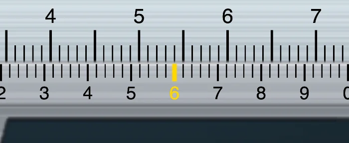
Hold a real 150 mm caliper next to most online simulators and one difference jumps out immediately: the vernier scale is numbered in tenths of a millimetre, not by division index. A 50-division vernier spans exactly 1 mm, so its numerals run 0 1 2 3 4 5 6 7 8 9 0 — ten numerals and then back to zero, because the scale has travelled one whole millimetre. It does not read 0 10 20 30 40 50. This simulator engraves it the real way.
That changes how you say the answer out loud. Each numbered line is a tenth of a millimetre, and the four or five small lines between numerals are the hundredths. So a coincidence three small divisions past numeral 4 is 0.4 + 3 × 0.02 = 0.46 mm, and the readout spells that bridge out for you as “numeral 4 + 3 div” beneath the VSR tile. On the 0.05 mm and 0.1 mm calipers the same rule applies with fewer divisions per tenth.
| Instrument | Vernier numerals | What one numeral is worth | Lines between numerals |
|---|---|---|---|
| 0.02 mm (50-div) | 0 1 2 … 9 0 | 0.1 mm | 4 |
| 0.05 mm (20-div) | 0 1 2 … 9 0 | 0.1 mm | 1 |
| 0.1 mm (10-div) | 0 1 2 … 9 0 | 0.1 mm | 0 |
| 0.001″ decimal inch (25-div) | 0 5 10 15 20 25 | 0.005″ | 4 |
| 1/128″ fractional inch (8-div) | 0 ⅛ ¼ … 1 | 1/8 of 1/16″ | 0 |
Inch calipers are the exception, and deliberately so. A 0.001″ vernier is genuinely numbered by division — 0 5 10 15 20 25 — because 25 divisions of 0.001″ do not land on a decimal tenth of anything convenient. Switch the simulator to Imperial and the numerals change accordingly; the metric rule is not applied to an inch scale.
mm or cm on the beam — both are correct
Real 150 mm calipers ship with the beam numbered either way: 10 20 30… in millimetres, or 1 2 3… in centimetres with the same graduation lines. Neither is more accurate — they are the same scale with different numerals — but a student who learned on one and is handed the other will misread it by a factor of ten. The mm | cm toggle above the canvas switches the beam numbering so you can practise on whichever engraving you actually own. It is display only: it changes no reading, no least count and no answer.
“Show me How?” — Watch the Reading Being Taken, Step by Step
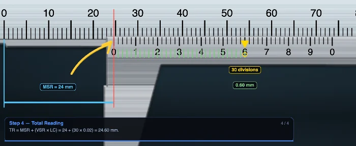
Reading a vernier is a skill of the eye, and a static diagram cannot teach it. Press Show me How? — the round play button at the bottom-right of the caliper — and the simulator takes the reading currently on the instrument and works through it on the metal itself, one step at a time. Nothing is read off a side panel; the arrows, the highlighted lines and the running count are drawn on the scales you are being taught to read.
- Main scale reading. A measuring line grows along the beam to the vernier zero, a red index line is carried up through the main scale, and an arrow lands on the last graduation it passed. The caption asks you to read it before it prints the answer.
- Find the coinciding line. The walkthrough works along the vernier ruling lines out one at a time and says how far each one misses by — each miss is exactly one least count larger than its neighbour — until one lands dead on. It deliberately tests one line past the match as well, so you see the coincidence is unique rather than merely the first thing tried.
- Count the divisions. The count walks from the vernier zero to that line, lighting each division as it passes. One box shows the running division count, the box below it shows what they are worth — 0.02, 0.04, 0.06… — which is VSR × LC shown as the repeated addition it really is.
- Total reading. The TR card's own rows are revealed one at a time, in the order you would write them.
- Zero error — shown only when the caliper actually has one, because a step that says “subtract 0.00” teaches nothing.
The view zooms itself to hold both ends of the reading on screen at once — the main-scale graduation and the coinciding vernier line can be 49 mm apart, so the magnification is solved from your reading rather than fixed in advance. While it runs, the MSR and VSR tiles start empty and fill in as the walkthrough derives them; the finished answer is never sitting on screen while the animation works towards it.
Controls. Play/pause with Space, step forward and back with → and ←, close with Esc — or use the four buttons on the canvas. Stepping lands on the start of each step, which is what you want when you are pausing on one for a class. The walkthrough is hidden in Quiz mode and in Practice until your attempt has been marked, because a step-by-step reading of the instrument is the answer you are being asked for.
How to Read a Vernier Caliper in Inches (0.001″)
An inch vernier caliper is read by exactly the same three steps as a metric one — only the divisions change. The beam is graduated in fortieths of an inch, so one main-scale division is 0.025″, and the vernier carries 25 divisions spanning 24 of them (0.600″ in total). Each vernier division is therefore 1/25 of a main division narrower:
LC = 1 MSD − 1 VSD = 0.025″ − (24/25 × 0.025″) = 0.025″ ÷ 25 = 0.001″
| Step | What you observe | Value |
|---|---|---|
| 1 | Last 0.025″ mark to the left of the vernier zero. The numbered lines are whole inches; the small numbers 1–9 between them are tenths (0.100″) | MSR = 1.350″ |
| 2 | The vernier division whose line is dead level with any main-scale line | VSR = 14 |
| 3 | VSR × LC | 14 × 0.001 = 0.014″ |
| 4 | Total reading | 1.350 + 0.014 = 1.364″ |
Machinists read this instrument in thousandths — 1.364″ is spoken as “one point three six four” or “one and three sixty-four thou”. Select Imperial then the 0.001″ precision pill above to reproduce this reading; the whole beam re-engraves in fortieths and the readout switches to three decimal places.
Imperial Vernier Caliper Least Counts — 0.001″ vs 1/128″
Two inch instruments are in common use, and they are read differently. Both are built into the simulator and share the same 0–4″ beam:
| Instrument | Main scale | 1 MSD | Vernier divisions | Vernier span | Least count | A reading looks like |
|---|---|---|---|---|---|---|
| Decimal inch | 40ths of an inch | 0.025″ | 25 (over 24 MSD) | 0.600″ | 0.001″ | 1.364″ |
| Fractional inch | 16ths of an inch | 1/16″ | 8 (over 7 MSD) | 7/16″ | 1/128″ | 1 43/128″ |
Which one you meet depends on the drawing. Machining and inspection work is dimensioned in thousandths, so the 0.001″ caliper is the shop standard; fitting, sheet-metal and fabrication drawings are dimensioned in halves, quarters, eighths and sixteenths, and the 1/128″ caliper is read directly in those terms without ever converting to a decimal. For reference, 1/128″ ≈ 0.0078″, so the fractional instrument is about eight times coarser than the decimal one.
How to Read a Fractional (1/128″) Vernier Caliper
A fractional caliper is read exactly like a metric one, except that every number in the sum is a fraction. Its beam is graduated in sixteenths of an inch and its vernier carries 8 divisions spanning 7 of them (7/16″), so one vernier division is 1/128″ narrower than one main division:
LC = 1 MSD − 1 VSD = 1/16″ − (7/8 × 1/16″) = 1/16″ ÷ 8 = 1/128″
| Step | What you observe | Value |
|---|---|---|
| 1 | Last sixteenth mark to the left of the vernier zero | MSR = 1 5/16″ |
| 2 | Vernier division that coincides with a main-scale line | VSR = 3 |
| 3 | VSR × LC | 3 × 1/128 = 3/128″ |
| 4 | Total reading, put over a common denominator | 1 40/128 + 3/128 = 1 43/128″ |
Reduce the answer only if it reduces cleanly: 1-43/128″ stays as it is, while 1-40/128″ is written 1-5/16″. Select the 1/128″ precision pill in Imperial mode to reproduce this reading, and note that the answer box in Practice and Quiz accepts fractions — 1 43/128, 1-43/128 or 43/128 — not just decimals.
Imperial Vernier Caliper Practice Problems and Reading Test
Every exercise in this simulator runs in inches as well as millimetres, so imperial reading practice needs no separate tool. Switch to Imperial, pick 0.001″ or 1/128″, then:
- Practice mode sets the jaws to a random inch opening and asks you to read it. On the fractional scale the answer box takes a fraction — type
1 43/128or43/128. Unreduced answers are accepted, so1 32/128is marked correct for 1-1/4″. - Measure an object clamps a real part in the jaws — a 5/8″ bearing ball reads a clean 0.625″, an M12 nut does not, and the difference is the lesson.
- Quiz mode is a five-question imperial reading test with a scored breakdown, and at least two questions make you close the jaws on a part before the scale means anything.
- Zero error can be switched on in inches too, stepping in whole least counts — ±0.005″ on the decimal caliper, ±5/128″ on the fractional one — so you practise applying the correction the way a real instrument forces you to.
If you are working through inch measurement more broadly, the micrometer screw gauge simulator reads to 0.001″ on its imperial barrel, and the steel ruler simulator covers reading a rule in sixteenths before a vernier is involved.
Worked Example — Measuring a 25.12 mm Shaft with a 0.02 mm Vernier
To make the formula concrete, here is a single full reading worked out the way it would happen in a workshop. You can reproduce these exact numbers in the simulator above by setting the precision pill to 0.02 mm and dragging the sliding jaw until the readout shows 25.12 mm.
| Step | What you observe | Value |
|---|---|---|
| 1 | Last full mm mark to the left of the vernier zero on the main scale | MSR = 25 mm |
| 2 | Vernier division that lines up cleanly with any main-scale line | VSR = 6 divisions |
| 3 | Least count of a 50-division vernier | LC = 0.02 mm |
| 4 | Total reading: TR = MSR + (VSR × LC) = 25 + (6 × 0.02) | TR = 25.12 mm |
The same shaft, measured on a coarser 0.05 mm 20-division vernier, would read MSR = 25, VSR = 2, TR = 25 + (2 × 0.05) = 25.10 mm. The 0.02 mm caliper resolves the extra 0.02 mm the 20-division scale rounds off — a clear demonstration of why least count matters when you compare instruments. The simulator’s Practice mode generates random target dimensions so you can repeat this calculation until the three-step pattern (MSR → VSR → TR) becomes automatic.
Five Mistakes Students Make — and How to Catch Them
From years of marking lab reports, the same handful of vernier errors appear again and again. Use the simulator to deliberately reproduce each one so you recognise it in your own readings.
- Reading the wrong main scale division. A common slip is picking the mm mark just after the vernier zero instead of just before it — producing a reading that is exactly 1 mm too large. Fix: always identify the mm mark that the vernier zero has already passed.
- Picking the “almost aligned” vernier line. Only one vernier division will be a true co-incidence; its neighbours are visibly above or below the main scale graduations. Tilt your head, or use the simulator’s Zoom button, to confirm the alignment before committing.
- Ignoring zero error. If the jaws are closed and the vernier zero is not on the main-scale zero, every single reading is wrong by that offset. Toggle Zero Error — On in the simulator to see how a +0.04 mm error silently inflates every measurement until you correct for it.
- Wrong sign on zero error. Even students who notice the offset often apply it the wrong way. Rule of thumb: if the vernier zero is to the right of the main zero, the error is positive and you subtract it; if it is to the left, the error is negative and you add the correction.
- Excessive jaw pressure on soft materials. Squeezing a plastic spacer or thin aluminium sheet between the outer jaws can compress the part by 0.05–0.10 mm — larger than the least count itself. Close the jaws using only the fine-adjustment roller until you feel a light contact.
What Is Zero Error in a Vernier Caliper?
Zero error occurs when the jaws are fully closed but the zero marks on the main scale and vernier scale do not align. Positive zero error means the vernier zero is to the right of the main scale zero — subtract the error from readings. Negative zero error means the vernier zero is to the left — add the correction. Always check for zero error before taking measurements.
Is there a 3D vernier caliper simulation?
Yes. Press 3D on the caliper's toolbar and the same instrument becomes an operable 3D model: drag the slider to move the jaws, drag the thumb roller for a fine feed, click the locking screw, and drag the background to look round it. It has four views - Reading (square to the scales), Whole, Measure and Parallax (what an eye off square reads) - and, while a part is loaded, an optional Close-up of the jaws on it in a corner. The Measure view cuts a bush open on the plane of the inside jaws, so you can see the two crossed knife edges touch the bore on its diameter, and cuts a block open to show the depth rod on the floor of a hole. It works with every least count in SI and Imperial, and Practice, Quiz and Show me How? all run in 3D, free in the browser on a phone, tablet or computer.
Why Is the Vernier Scale Numbered 0 1 2 … 9 0 Instead of 0 to 50?
Because a 50-division vernier spans exactly one millimetre, so its numerals count tenths of a millimetre and close back on zero after ten of them. That is how a real caliper is engraved, and it is why you say a reading as “numeral 4 plus 3 small divisions” rather than counting to 23. Numbering by division index — 0 10 20 30 40 50 — would give the same arithmetic but does not match any instrument you will be handed in a workshop. Decimal-inch verniers are the exception: those genuinely are numbered by division, 0 5 10 15 20 25.
Can I Watch a Vernier Caliper Reading Being Taken?
Yes. Press Show me How? on the caliper and the simulator animates the reading currently on the instrument in five steps — main scale, finding the coinciding line, counting the divisions, the total, and the zero-error correction — drawing each one on the scales themselves rather than in a side panel. It zooms to hold both ends of the reading on screen, empties the MSR and VSR tiles so the answer is not visible before it is derived, and can be paused and stepped with the space bar and arrow keys. It is available in Simulate mode and after a marked Practice attempt.
What Is the Difference Between a Vernier Caliper and a Micrometer?
A vernier caliper measures external, internal, and depth dimensions with a typical least count of 0.02 mm and range of 0–150 mm. A micrometer (screw gauge) reads to 0.01 mm but over a smaller range (0–25 mm per frame), and each pattern measures one kind of feature: an outside micrometer takes external dimensions, an inside or depth micrometer takes bores and depths. Use a vernier caliper for general-purpose work and a micrometer when higher accuracy matters — for a hole or step depth to 0.01 mm, the depth micrometer's base sits on the reference face while the caliper's depth rod has nothing to steady it.
What Is the Vernier Constant?
The vernier constant is another name for the least count. It equals the difference between one main scale division and one vernier scale division. For a 50-division vernier: 1 MSD − 1 VSD = 1 mm − 0.98 mm = 0.02 mm. This difference is what allows the vernier scale to resolve fractional millimetres that the main scale alone cannot measure.
What Are Common Sources of Error in Vernier Caliper Readings?
The main sources of error are: parallax error (reading the scale at an angle instead of straight-on), zero error (misaligned zero marks), thermal expansion (measuring hot workpieces), excessive jaw pressure (deforming soft materials), and worn jaws (giving inaccurate readings on old instruments). Practise correct technique using this simulator to eliminate these errors before working with real instruments.
When a Vernier Caliper Is the Wrong Instrument
A 0.02 mm vernier is a general-purpose workshop instrument, not a metrology lab tool. There are four situations where reaching for a different instrument is the correct call:
- You need tighter than 0.02 mm. Bearing fits, ground shafts, and reamed holes are typically specified to 0.01 mm or finer. Switch to a micrometer screw gauge (0.01 mm) or a digital micrometer (0.001 mm) for those.
- The feature is smaller than the jaw tip width. The outer jaws of a typical caliper are 3–5 mm wide near the tip, so groove widths or fine slot depths below that size cannot be entered. Use a feeler gauge set or a depth micrometer instead — the depth micrometer reads to 0.01 mm against the caliper's 0.02 mm, and its base bridges the feature instead of balancing on a thin rod.
- The part is hot, soft, or compliant. Steel expands roughly 0.012 mm per 100 mm per 10 °C. Measuring a part fresh off a lathe at 60 °C against a caliper at 20 °C gives a false +0.05 mm on a 100 mm length. Let parts equalise to room temperature, or use a non-contact instrument.
- The dimension is above 300 mm. Sliding caliper accuracy degrades as the beam flexes. Beam calipers, height gauges (see the Height Gauge simulator), or laser distance meters give better results above 300 mm.
Vernier Caliper Practice for US CTE and NIMS Programs
In US Career and Technical Education (CTE) machining programs, community college manufacturing courses, and apprenticeship training, the vernier caliper is commonly called a slide caliper — the same instrument, different shop name. The reading method is identical whether you call it a vernier caliper, slide caliper, or vernier scale caliper.
This simulator’s Imperial mode (SI / Imperial toggle in the controls bar) trains both the 0.001″ least count vernier scale found on US-standard slide calipers and the 1/128″ fractional scale still used wherever drawings are dimensioned in sixteenths — the exact instrument and precision level assessed in NIMS (National Institute for Metalworking Skills) Measurement, Materials and Safety credentialing examinations. NIMS credentials are nationally recognised across US manufacturing employers and are embedded in most state CTE machining pathways.
For students in NCCER (National Center for Construction Education and Research) pipefitting, millwright, and instrumentation programs, the same slide caliper skills apply — NCCER Core Curriculum and Pipefitting Level 1 both include precision measurement using vernier and digital calipers. The Practice and Quiz modes in this simulator replicate the timed measurement tasks common in both NIMS and NCCER practical assessments.
US high school CTE programs typically follow state-adopted standards aligned with the Manufacturing career cluster (one of the 16 CCTC career clusters). Within that cluster, the Production pathway requires students to demonstrate proficiency with precision hand tools including calipers to tolerances of ±0.002″ — equivalent to ±0.05 mm. This simulator covers that tolerance range in both metric and imperial modes.
What a Vernier Caliper Is Called Around the World
Same instrument, same reading method, different name depending on where you trained. If you searched in your own language and landed here, you are in the right place:
- Indonesian and Malay: jangka sorong — the standard term in Indonesian and Malaysian school physics, usually taught at 0.05 mm and 0.02 mm least count.
- Spanish: calibrador vernier, calibrador pie de rey, or simply pie de rey.
- Portuguese: paquímetro.
- English (UK and Commonwealth): vernier calliper — the double-L spelling is standard in British and Indian curricula.
- US shop floor: slide caliper, or just “calipers”.
The reading method does not change with the name: main scale, then the vernier division that lines up, then add. The simulator above behaves identically whichever term you learned it under.
Standards and References
The geometry, graduations and accuracy classes used in this simulator follow the international standards that govern real vernier instruments. Use these citations when you are writing a lab report or specifying a caliper for purchase:
- ISO 13385-1:2011 — Geometrical product specifications (GPS) — Dimensional measuring equipment — Part 1: Design and metrological characteristics of callipers. Defines the permissible maximum errors at different measuring lengths for vernier, dial and digital calipers.
- ASME B89.1.14-2018 — Calipers. The US standard (American Society of Mechanical Engineers) governing accuracy, repeatability, and calibration of vernier, dial, and digital calipers used in American manufacturing and inspection.
- BS 887:1982 — Specification for precision vernier callipers. The British Standard still cited in many UK and Commonwealth technical education syllabi.
- DIN 862 — The German equivalent, widely referenced in European manufacturers’ calibration certificates.
- Calibration practice: NIST-traceable calibration of a 6″ (150 mm) vernier caliper typically reports the error at five points (0, 1, 2, 4, 6″) against a class-1 gauge block set; the certificate is valid for 12 months under normal shop use.
The text above is reviewed against R. K. Jain’s Engineering Metrology (Khanna Publishers, Chapter 4) and the ISO 13385-1 working draft. If you find a graduation, formula, or class limit that disagrees with a current standard, report it — corrections are issued within 48 hours.
Explore Related Simulators
If you found this Vernier Caliper simulator helpful, explore our Dial Caliper simulator, Micrometer Screw Gauge simulator, Height Gauge simulator, Dial Gauge simulator, and Tolerance & Fits calculator for more hands-on practice. The micrometer also runs in 3D: open the Screw Gauge 3D simulation to turn the thimble by hand and cut the sleeve open to see the screw thread that sets its 0.01 mm least count.
Updated