Gas Turbine Simulator
Brayton Cycle & Jet Engine Lab — Power Plant • Turbojet • Turbofan • 2D & 3D

Display Controls
Press Start: the starter motor spins the spool, the igniters light the fuel at about 15 % speed, and the engine accelerates to idle at 62 %. The throttle then moves it along a stated running line between idle and the design point: pressure ratio − 1 grows as N², mass flow as N, and the turbine entry temperature rises from its idle value to the design value. Every reading is the full cycle solved at that point.
⚙ Losses, ambient & component details
Pressure losses in the regenerator and intercooler are neglected; the burner and reheater lose the fraction Δp/p you set. The power-plant cycle neglects the fuel’s mass in the turbine (the air-standard convention); the jet engines include it. Jets use a convergent propelling nozzle, which chokes when the nozzle pressure ratio exceeds its critical value.
Σ Live equations — values substituted from the current engine
📋 Station table — T, p, s, h and v at every station
⚡ Efficiency ladder — Carnot, ideal Brayton and the real engine
💡 What-if coach — insights from the current operating point
1 Overview
The Gas Turbine Simulator solves the Brayton cycle behind three engines: a power-plant gas turbine driving a generator, a turbojet and a separate-exhaust turbofan. Air is compressed, heated in the combustor to the turbine inlet temperature and expanded through the turbine; the power plant takes the surplus as shaft power, the jets take it as a fast jet. Every number on the page comes from that one solved cycle: the gas colour in the cutaway, the station numbers, the T–s and P–v diagrams, the readouts, the 3D engine and the step-by-step calculations.
Four modes: Simulate (the live engine), Explore (16 illustrated concept cards with worked examples), Practice (12 types of generated problems with full solutions) and Quiz (6 questions drawn from a pool of 22).
2 Choosing the engine and the view
The strip above the canvas picks the Engine — Power plant, Turbojet or Turbofan — and the View, 2D or 3D. A computer or tablet opens in 3D and a phone in 2D; your own choice is remembered. The Preset list then offers machines of that kind, from the textbook ideal cycle to an F-class power plant, a recuperated microturbine, an afterburning fighter turbojet and a high-bypass airliner turbofan at cruise and at take-off. Presets are representative classes of machine, not the data sheet of a particular product.
3 Simulate mode — the 2D cutaway and diagrams
The left of the canvas is the engine cut on its axis. Rotor blade rows turn, stators stand still, and the gas is coloured by its stagnation temperature from blue at the inlet to white-hot at the turbine inlet. Particles move faster where the gas is lighter and hotter. Station numbers follow the standard numbering (1–4 for the power plant; 0, 2, 13, 3, 4, 5, 6, 8, 18 for jets).
The right pane shows one of four diagrams: T–s (actual path solid, ideal isentropic path dashed, heat added and rejected shaded), P–v, Stations (temperature and pressure bars along the engine) and vs rp, which sweeps the pressure ratio and marks the optimum for maximum work and maximum efficiency (or specific thrust and TSFC for jets).
Use Pause to freeze the animation. Display Controls (top-left of the canvas) switch particles, temperature colours, station numbers, labels, the grid and the ideal path.
4 The 3D engine
In 3D the same engine is built as a real machine: casing, spinner or bellmouth, fan, compressor drum and blades, combustor with fuel nozzles, turbine discs and nozzle guide vanes, exhaust nozzle or diffuser, and the generator for the power plant. Drag to turn it, scroll or pinch to zoom, and click any part for a card that says what it does and gives its live numbers. Cutaway removes a quarter of the casing, X-ray makes it glass, and Exterior shows the engine closed. Hot parts glow at the colour their gas temperature implies.
5 Run engine — start-up, throttle and sound
Run engine opens a throttle panel. Start runs a start sequence: the starter motors the spool, the fuel lights off at about 15 % speed (watch the exhaust temperature jump), and the engine accelerates to idle at 62 %. The throttle then moves the engine along a simplified running line between idle and the design point: pressure ratio minus one grows with the square of spool speed, mass flow with spool speed, and the turbine entry temperature rises from its idle value to the design value. Shut down cuts the fuel and the spool runs down. Sound is synthesised in your browser and starts only when you press a button.
6 Controls and what they change
Pressure ratio rp = p2/p1 (overall for jets), turbine inlet temperature (TIT), the compressor and turbine isentropic efficiencies and the mass flow. Power plants add the ambient state and the Regenerator (effectiveness ε), Intercooler (two equal-ratio compressor stages, cooled back to the inlet temperature) and Reheat (two equal-ratio turbine stages, reheated to the TIT). Jets add altitude (ISA atmosphere), flight Mach number and the Afterburner; the turbofan adds bypass ratio, fan pressure ratio and fan efficiency. Gas model switches between the cold-air standard and a two-gas model with cp = 1.148 kJ/kg·K and k = 4/3 for the combustion products.
7 Reading the results
For a power plant: net power, thermal efficiency η = wnet/qin, back work ratio wc/wt, specific work, heat rate (3600/η, in kJ/kWh) and specific fuel consumption. For a jet: thrust F = ṁ[(1 + f)Vj − V0] plus pressure thrust, specific thrust F/ṁ, TSFC = ṁf/F, and thermal, propulsive and overall efficiencies. The calculator button opens every step for the current point. Export saves the station table as CSV or the canvas as PNG.
8 Explore, Practice and Quiz
Explore has four categories: Fundamentals, Improving the Cycle, Jet Propulsion and Real Engines; every worked number in a card is computed by the same solver. Practice generates a new problem each time (ideal efficiency, compressor exit temperature, back work ratio, optimum pressure ratio, regenerator temperature, heat rate, jet velocity, thrust, TSFC, propulsive efficiency, fuel–air ratio and the ISA atmosphere); type your answer, check it, or reveal the worked solution. Quiz asks six questions with shuffled options and scores you with stars.
9 SI and Imperial units
SI shows K, kPa, kJ/kg, MW, kN, N·s/kg and g/(kN·s). Imperial shows °R, psia, Btu/lbm, hp, lbf, lbf·s/lbm and lbm/(lbf·h). For example the textbook cycle’s 300 K inlet is 540 °R, and an airliner cruise TSFC of 17.5 g/(kN·s) is 0.62 lbm/(lbf·h). The canvas, the diagrams, the tables and the calculations all follow the switch, and your choice is remembered across the site.
10 Tips
Start with the Textbook ideal cycle and raise the pressure ratio: efficiency climbs while the net work peaks and falls. Switch to Textbook actual cycle and watch the back work ratio jump. Turn on the regenerator and push rp past about 13.7: the turbine exhaust becomes colder than the compressor delivery and the regenerator switches itself off, because it would now cool the air. On the turbofan, raise the bypass ratio at a fixed core and watch TSFC fall while specific thrust drops.
Gas Turbine Simulator: How the Brayton Cycle Works
A gas turbine runs on the Brayton cycle. A compressor raises the pressure of the air, a combustor burns fuel in it at almost constant pressure, a turbine expands the hot gas and takes work from it, and the gas leaves to the atmosphere. Because the turbine expands a hotter gas than the compressor compresses, it makes more work than the compressor needs. In a power station the surplus turns a generator; in a jet engine it accelerates the exhaust into a jet. This free gas turbine simulator solves that cycle for a power-plant gas turbine, a turbojet and a turbofan, and shows it as a 2D cutaway, a 3D engine and live T–s and P–v diagrams.
The Four Processes of the Brayton Cycle
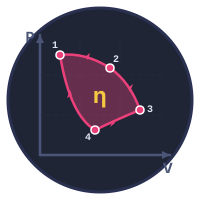
The ideal cycle has four processes: 1–2 isentropic compression in the compressor, 2–3 constant-pressure heat addition in the combustor, 3–4 isentropic expansion in the turbine and 4–1 constant-pressure heat rejection, which in an open-cycle engine is simply the exhaust mixing with the atmosphere. On the T–s diagram the compression and expansion are vertical lines and the two constant-pressure processes are rising curves; the area enclosed is the net work. On the P–v diagram the heat addition and rejection are horizontal lines.
Ideal Brayton Cycle Efficiency
With constant specific heats, the ideal Brayton cycle efficiency depends only on the pressure ratio rp:
ηBrayton = 1 − 1 / rp(k−1)/k
The table is the simulator’s own result for air (k = 1.4) between 300 K and 1300 K with ideal components.
| Pressure ratio rp | Thermal efficiency | Back work ratio | Net work (kJ/kg) |
|---|---|---|---|
| 4 | 32.7 % | 34.3 % | 280.8 |
| 6 | 40.1 % | 38.5 % | 321.9 |
| 8 | 44.8 % | 41.8 % | 340.6 |
| 10 | 48.2 % | 44.6 % | 349.2 |
| 15 | 53.9 % | 50.0 % | 351.7 |
| 20 | 57.5 % | 54.3 % | 343.3 |
| 30 | 62.2 % | 61.0 % | 316.9 |
| 40 | 65.1 % | 66.2 % | 287.6 |
Efficiency keeps rising with pressure ratio, but the net work per kilogram of air peaks and then falls: at a high pressure ratio the compressor delivers air so hot that little fuel can be added before the turbine inlet temperature limit is reached.
Ideal vs Actual Brayton Cycle: Isentropic Efficiency and Back Work Ratio
A real compressor needs more work than an isentropic one, and a real turbine gives less. The isentropic efficiencies are ηc = (T2s − T1)/(T2 − T1) and ηt = (T3 − T4)/(T3 − T4s). The back work ratio, wc/wt, is the share of the turbine’s work that goes back into the compressor. It is large in every gas turbine because a gas, with its large specific volume, is expensive to compress. The table repeats the cycle above with ηc = 0.80 and ηt = 0.85, with and without an 80 % regenerator:
| rp | Efficiency | Back work ratio | Net work (kJ/kg) | With regenerator | Compressor exit T2 (K) | Turbine exit T4 (K) |
|---|---|---|---|---|---|---|
| 4 | 21.9 % | 50.4 % | 180.0 | 39.6 % | 482 | 939 |
| 6 | 25.6 % | 56.6 % | 193.0 | 38.1 % | 551 | 857 |
| 8 | 27.4 % | 61.5 % | 191.7 | 35.6 % | 604 | 805 |
| 10 | 28.2 % | 65.5 % | 184.6 | 33.0 % | 649 | 767 |
| 15 | 28.0 % | 73.6 % | 158.1 | 28.0 % | 738 | 705 |
| 20 | 26.0 % | 79.9 % | 128.6 | 26.0 % | 808 | 665 |
The ideal cycle at rp = 8 converts 44.8 % of its heat; the real one converts 27.4 %, and 61.5 % of its turbine work goes straight back into the compressor. A real cycle also has a pressure ratio of maximum efficiency, which the ideal cycle does not.
Regeneration, Intercooling and Reheat
A regenerator (recuperator) uses the hot turbine exhaust to preheat the compressed air before the combustor, so less fuel is needed for the same turbine inlet temperature. Its effectiveness is ε = (Tx − T2)/(T4 − T2). It only helps while the turbine exhaust is hotter than the compressor delivery: for the cycle above that stops at a pressure ratio of about 13.7, and the simulator switches the regenerator off beyond it rather than let it cool the air. That is why regenerated machines, such as microturbines, use low pressure ratios.
Intercooling splits the compression into two stages and cools the air between them, cutting the compressor work. Reheat splits the expansion and heats the gas again between turbines, raising the turbine work. Each raises the net work but, on its own, lowers the efficiency of a cycle without a regenerator, because the extra heat is added or rejected at less favourable temperatures. Combined with regeneration, which recovers the hotter exhaust and the cooler compressor delivery, they push the cycle towards the Ericsson cycle: the textbook intercooled, reheated, regenerated cycle in the presets reaches 50.9 % with ηc = 0.85 and ηt = 0.88 at rp = 8.
Optimum Pressure Ratio and Turbine Inlet Temperature
For a fixed turbine inlet temperature T3, the ideal cycle’s net work is greatest when the compressor exit and turbine exit temperatures are equal, at
rp,opt = (T3/T1)k/[2(k−1)]
With T1 = 300 K and T3 = 1200 K this is 41.75 = 11.3. With component efficiencies the optimum for work becomes (ηcηtT3/T1)k/[2(k−1)]: 6.63 for the textbook actual cycle at 1300 K, whose efficiency peaks at a different, higher ratio of 11.9. The vs rp diagram draws both curves and both optima for whatever engine is on screen. Raising the turbine inlet temperature raises both work and efficiency, which is why turbine blades are cooled with compressor air and coated with thermal barrier ceramics so that the gas can be hotter than the metal can stand.
Jet Engine Simulator: Turbojet vs Turbofan
A jet engine is a gas turbine whose turbine drives only the compressor (and the fan). The rest of the energy leaves as a jet. The thrust of a turbojet is
F = ṁa[(1 + f)Vj − V0] + (pe − pa)Ae
where f is the fuel–air ratio, Vj the jet velocity, V0 the flight speed and the last term the pressure thrust of a choked convergent nozzle. Thrust specific fuel consumption, TSFC = ṁf/F, is the jet engine’s fuel economy, and the propulsive efficiency ηp ≈ 2V0/(Vj + V0) explains the turbofan: making thrust by accelerating a lot of air a little wastes less kinetic energy than accelerating a little air a lot. The simulator’s presets give:
| Preset | Flight condition | Thrust | Specific thrust | TSFC | Propulsive efficiency, FV0/(FV0 + wake KE) |
|---|---|---|---|---|---|
| Teaching turbojet | Sea level, static | 14.07 kN | 703 N·s/kg | 28.20 g/(kN·s) | — (V0 = 0) |
| Turbojet at cruise | 11 km, Mach 0.8 | 28.23 kN | 706 N·s/kg | 35.09 g/(kN·s) | 41.1 % |
| Afterburning fighter turbojet | 9 km, Mach 1.6 | 66.45 kN | 886 N·s/kg | 55.68 g/(kN·s) | 54.9 % |
| High-bypass turbofan (BPR 9) | 11 km, Mach 0.8 | 67.03 kN | 149 N·s/kg | 17.47 g/(kN·s) | 69.2 % |
| Low-bypass turbofan (BPR 0.6) | 11 km, Mach 0.9 | 56.92 kN | 569 N·s/kg | 31.91 g/(kN·s) | 44.9 % |
The high-bypass turbofan uses half the fuel per newton of the cruise turbojet at the same speed and height. Its specific thrust is much lower, which is why its fan and nacelle are so large. The afterburner buys thrust at a steep price in fuel: reheating the jet adds thrust but at a low pressure, so the extra heat is used inefficiently.
Turboprops and Turboshafts
A turboprop or turboshaft is a gas turbine that, like the power plant, takes almost all its surplus as shaft power, through a free power turbine, to drive a propeller, a helicopter rotor, a pump or a generator. The Power plant engine in this simulator is the cycle behind all of them.
Gas Turbine Efficiency in Power Plants: Simple vs Combined Cycle
A large simple-cycle gas turbine converts about 35 to 42 % of the fuel’s energy into electricity; the F-class preset here gives 41.0 %. Its exhaust leaves at 850–900 K, hot enough to raise steam in a heat recovery steam generator and run a Rankine cycle on top: that combined cycle reaches about 60 %. The heat rate, 3600/η in kJ/kWh, is the number a power-station engineer quotes: lower is better.
3D Gas Turbine: Turn It, Cut It Open, Click a Part
Switch the view to 3D and the engine appears as a real machine you can turn. The cutaway removes a quarter of the casing so the compressor drum, the combustor, the turbine and the shafts can be seen working; click any part to learn what it does. The 3D engine is built from the same solved cycle: the hot section glows at the colour of its gas temperature and the spools turn faster as you open the throttle.
Who Uses This Simulator?
Mechanical and aerospace engineering students working through the gas power cycles chapter of a thermodynamics course (Cengel & Boles chapter 9, Saravanamuttoo’s Gas Turbine Theory), vocational trainees in power generation and aviation maintenance, and teachers who want a free online Brayton cycle simulator and jet engine simulator that shows the cycle, the machine and the numbers on one screen.
Frequently Asked Questions
What is the efficiency of an ideal Brayton cycle?
The ideal Brayton cycle efficiency is 1 - 1/rp^((k-1)/k), where rp is the compressor pressure ratio and k is 1.4 for air. It depends only on the pressure ratio: 44.8 percent at rp = 8 and 48.2 percent at rp = 10. A real gas turbine is lower because the compressor and turbine are not isentropic; simple-cycle power plants run at about 35 to 42 percent.
Why is the back work ratio so high in a gas turbine?
The compressor handles a gas, which has a large specific volume, so compressing it takes a large share of the turbine's output. In a gas turbine 40 to 80 percent of the turbine work drives the compressor, against a few percent for the pump of a steam plant. With rp = 8 between 300 K and 1300 K the ideal back work ratio is 41.8 percent; with a compressor efficiency of 0.80 and a turbine efficiency of 0.85 it rises to 61.5 percent.
What is the optimum pressure ratio for maximum net work in a Brayton cycle?
For a fixed turbine inlet temperature the ideal cycle's net work is greatest at rp = (T3/T1)^(k/(2(k-1))). With T1 = 300 K and T3 = 1200 K that is 11.3. With component efficiencies the optimum falls to (ηc ηt T3/T1)^(k/(2(k-1))), and the pressure ratio for maximum efficiency is higher than the one for maximum work.
What is the difference between a turbojet and a turbofan?
A turbojet sends all its air through the core and makes thrust from one fast, hot jet. A turbofan uses part of the turbine work to drive a large fan, and most of its air bypasses the core as a slower cold jet. Accelerating more air by less gives a higher propulsive efficiency, about 2V0/(Vj + V0), so a high-bypass turbofan burns far less fuel per unit of thrust at airliner speeds.
Selected References
- Cengel, Y. A. & Boles, M. A. — Thermodynamics: An Engineering Approach, 9th ed., Chapter 9 (Gas Power Cycles).
- Saravanamuttoo, H. I. H., Rogers, G. F. C., Cohen, H. & Straznicky, P. V. — Gas Turbine Theory, 7th ed., Chapters 2–3.
- Mattingly, J. D. — Elements of Propulsion: Gas Turbines and Rockets, AIAA.
- ICAO Doc 7488 — Manual of the ICAO Standard Atmosphere.
Explore Related Simulators
For the other gas power cycles, open the Four Stroke Engine Simulator (Otto and Diesel), and for the steam cycle that sits on top of a gas turbine in a combined-cycle plant, the Rankine Cycle Simulator. The Thermodynamics Simulator covers the processes the Brayton cycle is built from, the Airfoil Analysis tool the lift that compressor and turbine blades rely on, and the Refrigeration Cycle the reversed version of a heat engine.
Updated